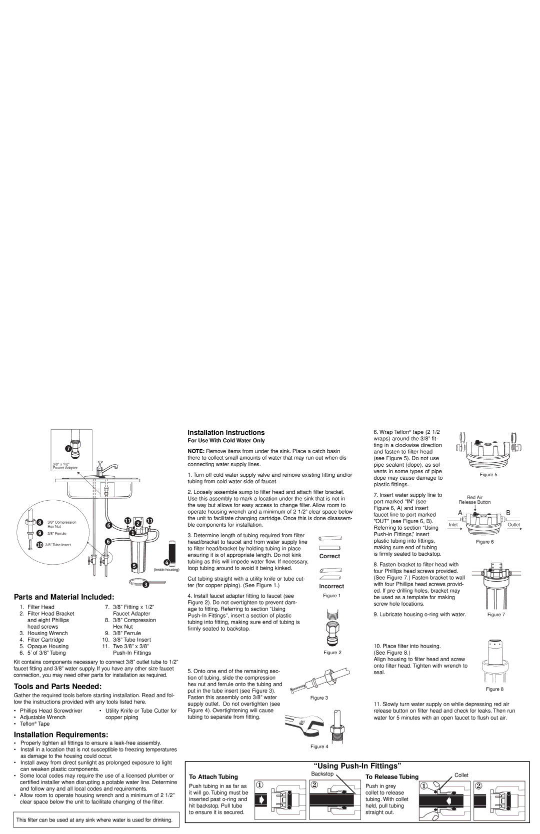
3/8" x 1/2" Faucet Adapter
Installation Instructions
For Use With Cold Water Only
NOTE: Remove items from under the sink. Place a catch basin there to collect small amounts of water that may run out when dis- connecting water supply lines.
1. Turn off cold water supply valve and remove existing fitting and/or |
tubing from cold water side of faucet. |
2. Loosely assemble sump to filter head and attach filter bracket. |
6. Wrap Teflon® tape (2 1/2 wraps) around the 3/8” fit- ting in a clockwise direction and fasten to filter head (see Figure 5). Do not use pipe sealant (dope), as sol- vents in some types of pipe
Figure 5
dope may cause damage to plastic fittings.
3/8" Compression Hex Nut
Use this assembly to mark a location under the sink that is not in |
the way but allows for easy access to change filter. Allow room to |
operate housing wrench and a minimum of 2 1/2” clear space below |
the unit to facilitate changing cartridge. Once this is done disassem- |
ble components for installation. |
7. Insert water supply line to |
port marked "IN" (see |
Figure 6, A) and insert |
faucet line to port marked |
"OUT" (see Figure 6, B). |
Referring to section “Using |
Red Air
Release Button
AB
InletOutlet
3/8" Ferrule
3/8" Tube Insert
3. Determine length of tubing required from filter |
head/bracket to faucet and from water supply line |
to filter head/bracket by holding tubing in place |
ensuring it is of appropriate length. Do not kink |
tubing as this will impede water flow. If necessary, |
Correct
plastic tubing into fittings, |
making sure end of tubing |
is firmly seated to backstop. |
Figure 6
Parts and Material Included:
1. | Filter Head | 7. | 3/8” Fitting x 1/2” |
2. | Filter Head Bracket |
| Faucet Adapter |
| and eight Phillips | 8. | 3/8” Compression |
| head screws |
| Hex Nut |
3. | Housing Wrench | 9. | 3/8” Ferrule |
4. | Filter Cartridge | 10. | 3/8” Tube Insert |
loop tubing around to avoid it being kinked. |
Cut tubing straight with a utility knife or tube cut- ter (for copper piping). (See Figure 1.)
4.Install faucet adapter fitting to faucet (see Figure 2). Do not overtighten to prevent dam- age to fitting. Referring to section “Using
Incorrect
Figure 1
8. Fasten bracket to filter head with four Phillips head screws provided. (See Figure 7.) Fasten bracket to wall with four Phillips head screws provid- ed. If
9. Lubricate housing | Figure 7 |
5. | Opaque Housing | 11. Two 3/8” x 3/8” |
6. | 5’ of 3/8” Tubing |
Kit contains components necessary to connect 3/8” outlet tube to 1/2” faucet fitting and 3/8” water supply. If you have any other size faucet connection, you may need other parts for installation as required.
Tools and Parts Needed:
Gather the required tools before starting installation. Read and fol- low the instructions provided with any tools listed here.
• | Phillips Head Screwdriver | • Utility Knife or Tube Cutter for |
• | Adjustable Wrench | copper piping |
• | Teflon® Tape |
|
Installation Requirements:
• Properly tighten all fittings to ensure a | |
• | Install in a location that is not susceptible to freezing temperatures |
| as damage to the housing could occur. |
• | Install away from direct sunlight as prolonged exposure to light |
Figure 2
5.Onto one end of the remaining sec- tion of tubing, slide the compression
hex nut and ferrule onto the tubing and |
|
put in the tube insert (see Figure 3). |
|
Fasten this assembly onto 3/8” water | Figure 3 |
supply outlet. Do not overtighten (see |
|
Figure 4). Overtightening will cause |
|
tubing to separate from fitting. |
|
| Figure 4 |
10. Place filter into housing. (See Figure 8.)
Align housing to filter head and screw onto filter head. Tighten with wrench to seal.
Figure 8
11.Slowly turn water supply on while depressing red air release button on filter head and check for leaks. Then run water for 5 minutes with an open faucet to flush out air.
can weaken plastic components. |
“Using Push-In Fittings”
• | Some local codes may require the use of a licensed plumber or |
| certified installer when disrupting a potable water line. Determine |
| and follow any and all local codes and requirements. |
• | Allow room to operate housing wrench and a minimum of 2 1/2” |
| clear space below the unit to facilitate changing of the filter. |
This filter can be used at any sink where water is used for drinking.
To Attach Tubing
Push tubing in as far as it will go. Tubing must be inserted past
Backstop |
To Release Tubing
Push in grey collet to release tubing. With collet held, pull tubing straight out.
Collet |