Fig. 35
INSTALLATION OF PILOT SAFETY SWITCH
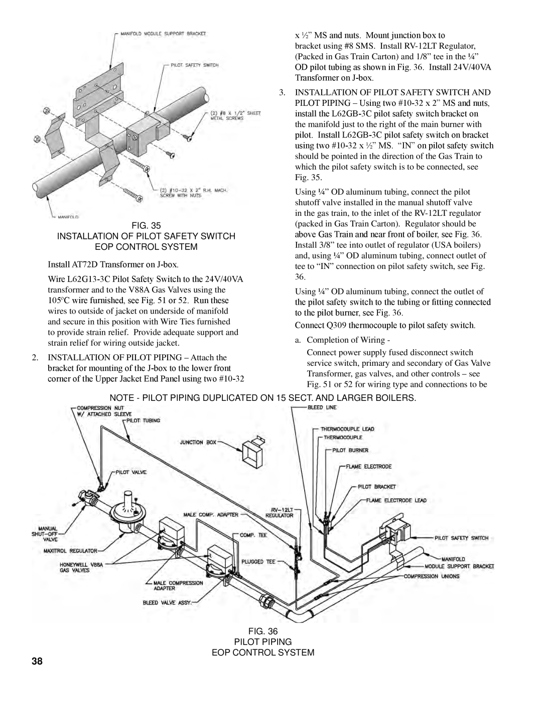
EOP CONTROL SYSTEM
Install AT72D Transformer on
Wire
2.INSTALLATION OF PILOT PIPING – Attach the bracket for mounting of the
x ½” MS and nuts. Mount junction box to bracket using #8 SMS. Install
OD pilot tubing as shown in Fig. 36. Install 24V/40VA Transformer on
3.INSTALLATION OF PILOT SAFETY SWITCH AND
PILOT PIPING – Using two
Using ¼” OD aluminum tubing, connect the pilot shutoff valve installed in the manual shutoff valve in the gas train, to the inlet of the
Install 3/8” tee into outlet of regulator (USA boilers) and, using ¼” OD aluminum tubing, connect outlet of tee to “IN” connection on pilot safety switch, see Fig.
36.
Using ¼” OD aluminum tubing, connect the outlet of the pilot safety switch to the tubing or fitting connected to the pilot burner, see Fig. 36.
Connect Q309 thermocouple to pilot safety switch.
a.Completion of Wiring -
Connect power supply fused disconnect switch service switch, primary and secondary of Gas Valve Transformer, gas valves, and other controls – see Fig. 51 or 52 for wiring type and connections to be
Note - Pilot Piping duplicated on 15 sect. and larger boilers.
38
Fig. 36