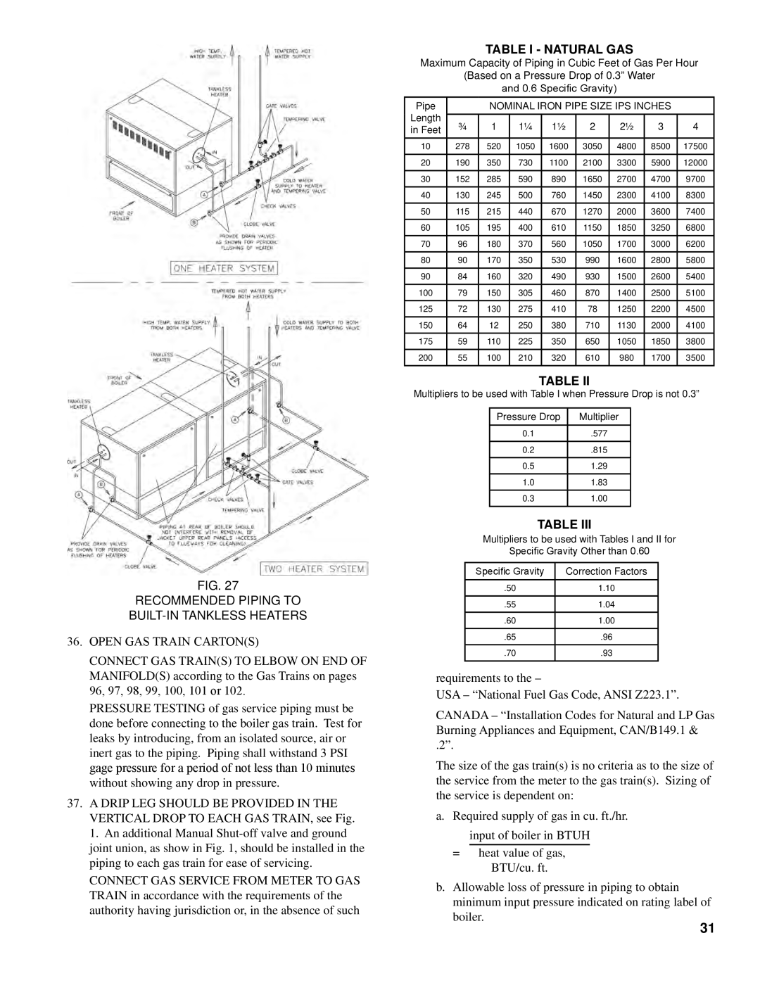
Fig. 27
RECOMMENDED PIPING TO
BUILT-IN TANKLESS HEATERS
36.OPEN GAS TRAIN CARTON(S)
CONNECT GAS TRAIN(S) TO ELBOW ON END OF MANIFOLD(S) according to the Gas Trains on pages
96, 97, 98, 99, 100, 101 or 102.
PRESSURE TESTING of gas service piping must be done before connecting to the boiler gas train. Test for leaks by introducing, from an isolated source, air or inert gas to the piping. Piping shall withstand 3 PSI gage pressure for a period of not less than 10 minutes without showing any drop in pressure.
37.A DRIP LEG SHOULD BE PROVIDED IN THE VERTICAL DROP TO EACH GAS TRAIN, see Fig.
1. An additional Manual
CONNECT GAS SERVICE FROM METER TO GAS TRAIN in accordance with the requirements of the authority having jurisdiction or, in the absence of such
TABLE I - NATURAL GAS
Maximum Capacity of Piping in Cubic Feet of Gas Per Hour
(Based on a Pressure Drop of 0.3” Water
and 0.6 Specific Gravity)
Pipe |
| NOMINAL IRON PIPE SIZE IPS INCHES |
| ||||||
Length |
|
|
|
|
|
|
|
| |
¾ | 1 | 1¼ | 1½ | 2 | 2½ | 3 | 4 | ||
in Feet | |||||||||
|
|
|
|
|
|
|
|
| |
10 | 278 | 520 | 1050 | 1600 | 3050 | 4800 | 8500 | 17500 | |
|
|
|
|
|
|
|
|
| |
20 | 190 | 350 | 730 | 1100 | 2100 | 3300 | 5900 | 12000 | |
|
|
|
|
|
|
|
|
| |
30 | 152 | 285 | 590 | 890 | 1650 | 2700 | 4700 | 9700 | |
|
|
|
|
|
|
|
|
| |
40 | 130 | 245 | 500 | 760 | 1450 | 2300 | 4100 | 8300 | |
|
|
|
|
|
|
|
|
| |
50 | 115 | 215 | 440 | 670 | 1270 | 2000 | 3600 | 7400 | |
|
|
|
|
|
|
|
|
| |
60 | 105 | 195 | 400 | 610 | 1150 | 1850 | 3250 | 6800 | |
70 | 96 | 180 | 370 | 560 | 1050 | 1700 | 3000 | 6200 | |
|
|
|
|
|
|
|
|
| |
80 | 90 | 170 | 350 | 530 | 990 | 1600 | 2800 | 5800 | |
90 | 84 | 160 | 320 | 490 | 930 | 1500 | 2600 | 5400 | |
|
|
|
|
|
|
|
|
| |
100 | 79 | 150 | 305 | 460 | 870 | 1400 | 2500 | 5100 | |
125 | 72 | 130 | 275 | 410 | 78 | 1250 | 2200 | 4500 | |
|
|
|
|
|
|
|
|
| |
150 | 64 | 12 | 250 | 380 | 710 | 1130 | 2000 | 4100 | |
|
|
|
|
|
|
|
|
| |
175 | 59 | 110 | 225 | 350 | 650 | 1050 | 1850 | 3800 | |
|
|
|
|
|
|
|
|
| |
200 | 55 | 100 | 210 | 320 | 610 | 980 | 1700 | 3500 | |
|
|
|
|
|
|
|
|
| |
TABLE II
Multipliers to be used with Table I when Pressure Drop is not 0.3”
Pressure Drop | Multiplier |
0.1 | .577 |
0.2 | .815 |
|
|
0.5 | 1.29 |
1.0 | 1.83 |
|
|
0.3 | 1.00 |
TABLE III
Multipliers to be used with Tables I and II for | ||
Specific Gravity Other than 0.60 | ||
|
|
|
Specific Gravity | Correction Factors |
|
.50 | 1.10 |
|
|
|
|
.55 | 1.04 |
|
|
|
|
.60 | 1.00 |
|
.65 | .96 |
|
|
|
|
.70 | .93 |
|
requirements to the –
USA – “National Fuel Gas Code, ANSI Z223.1”.
CANADA – “Installation Codes for Natural and LP Gas Burning Appliances and Equipment, CAN/B149.1 &
.2”.
The size of the gas train(s) is no criteria as to the size of the service from the meter to the gas train(s). Sizing of the service is dependent on:
a.Required supply of gas in cu. ft./hr. input of boiler in BTUH
= heat value of gas, BTU/cu. ft.
b. Allowable loss of pressure in piping to obtain minimum input pressure indicated on rating label of boiler.
31