SECTION II – GENERAL INFORMATION
1.BOILER INSTALLATION must conform to the requirements of the authority having jurisdiction, or in the absence of such requirements, to:
USA – “National Fuel Gas Code, ANSI Z223.1”.
When required by the authority having jurisdiction, the installation must conform to American Society of Mechanical Engineers Safety Code for Controls and Safety Devices for Automatically Fired Boilers, No.
CANADA – “Installation Codes for Natural and Propane Gas Burning Appliances and Equipment,
DO NOT INSTALL THIS BOILER ON CARPETING.
2.BOILER LOCATION – locate on a level NON- COMBUSTIBLE FLOOR as close as possible to chimney so that vent connection is short and direct.
DANGER
Boilermustnotbeinstalleddirectlyoncombustible flooring. A concrete pad is not sufficient to protect combustible flooring.
The boiler shall be installed such that the gas ignition system components are protected from water (dripping, spraying, rain, etc.) during boiler operation and service (circulator replacement, control replacement, etc.).
Do not install boiler where gasoline or other flammable vapors or liquids, or sources of hydrocarbons (i.e. bleachers, cleaners, chemicals, sprays, paint removers, fabric softeners, etc. ) are used or stored.
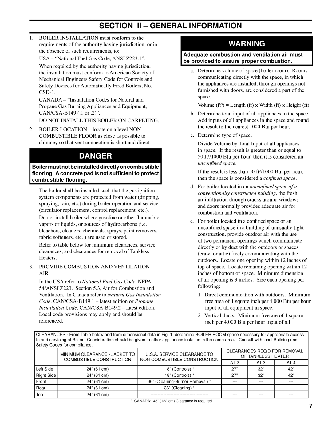
Refer to table below for minimum clearances, service clearances, and clearances for removal of Tankless Heaters.
3.PROVIDE COMBUSTION AND VENTILATION AIR.
In the USA refer to National Fuel Gas Code, NFPA 54/ANSI Z223. Section 5.3, Air for Combustion and Ventilation. In Canada refer to Natural Gas Installation Code,
WARNING
Adequate combustion and ventilation air must be provided to assure proper combustion.
a.Determine volume of space (boiler room). Rooms communicating directly with the space, in which the appliances are installed, through openings not furnished with doors, are considered a part of the space.
Volume (ft³) = Length (ft) x Width (ft) x Height (ft)
b.Determine total input of all appliances in the space. Add inputs of all appliances in the space and round the result to the nearest 1000 Btu per hour.
c.Determine type of space.
Divide Volume by Total Input of all appliances in space. If the result is greater than or equal to
50ft³/1000 Btu per hour, then it is considered an unconfined space.
If the result is less than 50 ft³/1000 Btu per hour, then the space is considered a confined space.
d.For boiler located in an unconfined space of a conventionally constructed building, the fresh air infiltration through cracks around windows and doors normally provides adequate air for combustion and ventilation.
e.For boiler located in a confined space or an unconfined space in a building of unusually tight construction, provide outdoor air with the use of two permanent openings which communicate directly or by duct with the outdoors or spaces (crawl or attic) freely communicating with the outdoors. Locate one opening within 12 inches of top of space. Locate remaining opening within 12 inches of bottom of space. Minimum dimension of air opening is 3 inches. Size each opening per following:
1.Direct communication with outdoors. Minimum free area of 1 square inch per 4,000 Btu per hour input of all equipment in space.
2.Vertical ducts. Minimum free are of 1 square inch per 4,000 Btu per hour input of all
CLEARANCES - From Table below and from dimensional data in Fig. 1, determine BOILER ROOM space necessary for appropriate access to and servicing of Boiler. Consideration should be given to other appliances installed in the same area. Consult with local Building and Safety Codes for compliance.
| MINIMUM CLEARANCE - JACKET TO | U.S.A. SERVICE CLEARANCE TO | CLEARANCES REQ’D FOR REMOVAL | |||
|
| OF TANKLESS HEATER | ||||
| COMBUSTIBLE CONSTRUCTION |
| ||||
|
| |||||
|
|
|
| |||
Left Side | 24” (61 cm) | 18” (Controls) * | 27” |
| 32” | 42” |
Right Side | 24” (61 cm) | 18” (Controls) * | 27” |
| 32” | 42” |
Front | 24” (61 cm) | 36” |
| |||
Rear | 24” (61 cm) | 36” (Cleaning) * |
| |||
Top | 24” (61 cm) |
| ||||
| * CANADA: 48” (122 cm) Clearance is required |
|
|
|
| |
