thermocouple proves pilot flame and, in the absence of such, will cool and, within 45 to 90 seconds, will cause the
The 5015B thru 5024B boilers utilize two Thermocouple Control Systems that are interconnected electrically thru all operating and safety controls. Should any of the aforementioned controls break the power supply circuit, both Thermocouple Control Systems would be
a.LIGHTING INSTRUCTIONS
(1)Make sure that all main manual and pilot valves have been off for at least five (5) minutes.
(2)Set operating and limit controls to desired setting.
(3)Open pilot valve.
(4)Depress button on pilot safety switch to which it is connected and hold lighted match on pilot. Hold button in for at least one minute, or until the pilot burner remains lit after the button is released. Repeat for second pilot when boiler is so equipped.
(5)Open manual main
(6)Turn on main electric switch.
NORMAL OPERATION SEQUENCE
5006B thru 5013B, see Fig. 55
5015B thru 5024B, see Fig. 56
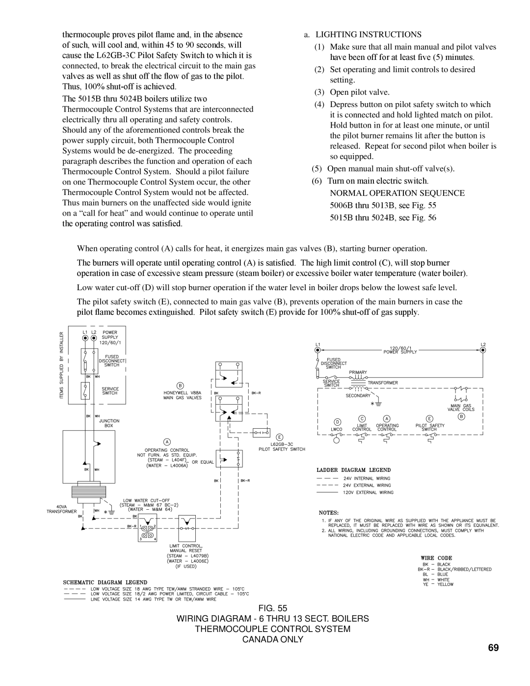
When operating control (A) calls for heat, it energizes main gas valves (B), starting burner operation.
The burners will operate until operating control (A) is satisfied. The high limit control (C), will stop burner operation in case of excessive steam pressure (steam boiler) or excessive boiler water temperature (water boiler).
Low water
The pilot safety switch (E), connected to main gas valve (B), prevents operation of the main burners in case the pilot flame becomes extinguished. Pilot safety switch (E) provide for 100%
Fig. 55
WIRING DIAGRAM - 6 THRU 13 SECT. BOILERS
THERMOCOUPLE CONTROL SYSTEM
CANADA ONLY
69