equipment in space. Duct
3.Horizontal ducts. Minimum free area of 1 square inch per 2,000 Btu per hour input of all equipment in space. Duct
Alternate method for boiler located within confined space. Use indoor air if two permanent openings communicate directly with additional space(s) of sufficient volume such that combined volume of all spaces meet criteria for unconfined space. Size each opening for minimum free area of 1 square inch per 1,000 Btu per hour input of all equipment in spaces, but not less than 100 square inches.
4.Louvers and Grilles of Ventilation Ducts
All outside openings should be screened and louvered. Screens used should not be smaller than ¼ inch mesh. Louvers will prevent the entrance of rain and snow.
a.Free area requirements need to consider the blocking effect of louvers, grilles, or screens protecting the openings. If the free area of the louver or grille
is not known, assume wood louvers have
b.Louvers and grilles must be fixed in the open position or interlocked with the equipment to open automatically during equipment operation.
SECTION III – INSTALLATION INSTRUCTIONS
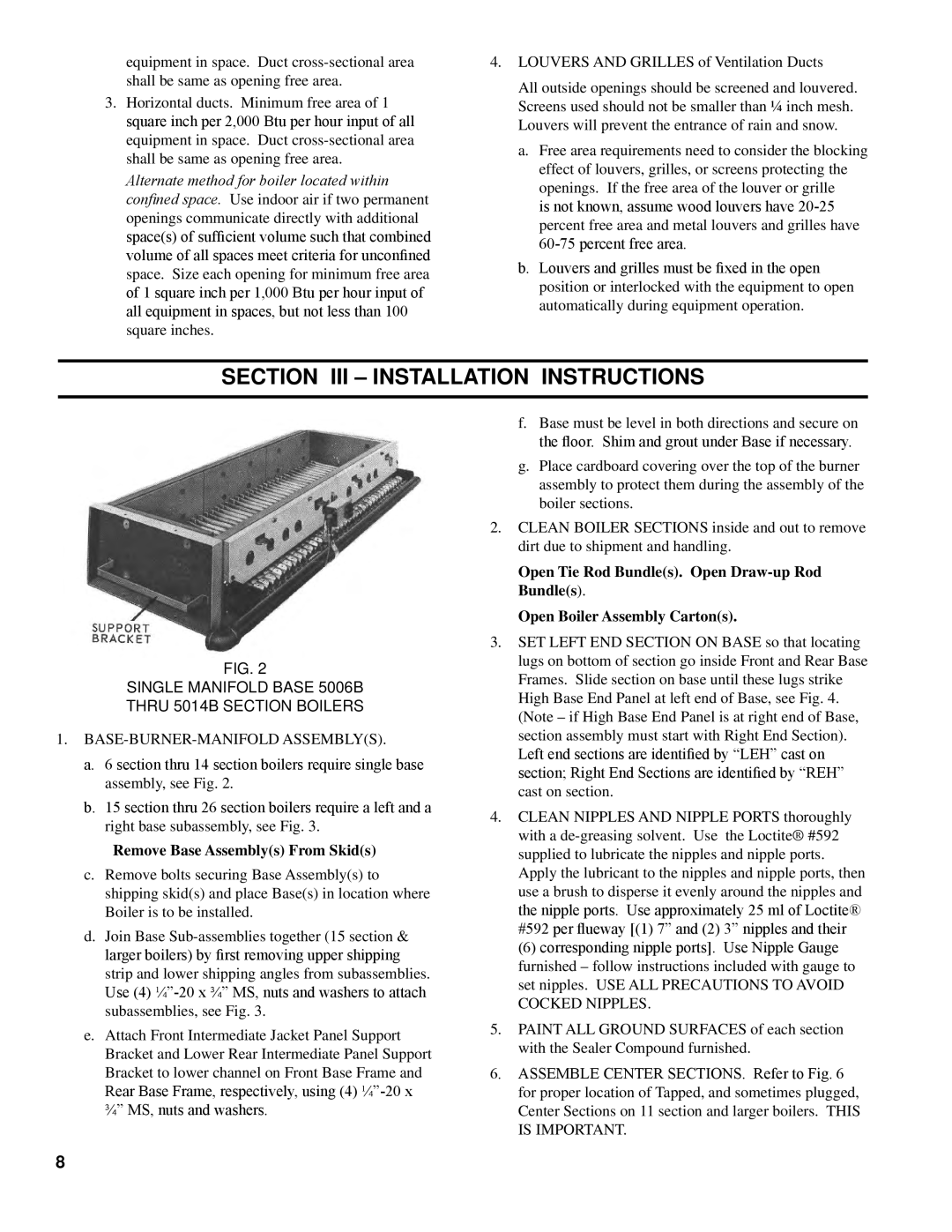
Fig. 2
SINGLE MANIFOLD BASE 5006B
THRU 5014B SECTION BOILERS
1.BASE-BURNER-MANIFOLD ASSEMBLY(S).
a.6 section thru 14 section boilers require single base assembly, see Fig. 2.
b.15 section thru 26 section boilers require a left and a right base subassembly, see Fig. 3.
Remove Base Assembly(s) From Skid(s)
c.Remove bolts securing Base Assembly(s) to shipping skid(s) and place Base(s) in location where Boiler is to be installed.
d.Join Base
Use (4)
e.Attach Front Intermediate Jacket Panel Support Bracket and Lower Rear Intermediate Panel Support Bracket to lower channel on Front Base Frame and
Rear Base Frame, respectively, using (4)
f.Base must be level in both directions and secure on the floor. Shim and grout under Base if necessary.
g.Place cardboard covering over the top of the burner assembly to protect them during the assembly of the boiler sections.
2.CLEAN BOILER SECTIONS inside and out to remove dirt due to shipment and handling.
Open Tie Rod Bundle(s). Open
Open Boiler Assembly Carton(s).
3.SET LEFT END SECTION ON BASE so that locating lugs on bottom of section go inside Front and Rear Base Frames. Slide section on base until these lugs strike High Base End Panel at left end of Base, see Fig. 4. (Note – if High Base End Panel is at right end of Base, section assembly must start with Right End Section).
Left end sections are identified by “LEH” cast on section; Right End Sections are identified by “REH” cast on section.
4.CLEAN NIPPLES AND NIPPLE PORTS thoroughly with a
(6) corresponding nipple ports]. Use Nipple Gauge furnished – follow instructions included with gauge to set nipples. USE ALL PRECAUTIONS TO AVOID COCKED NIPPLES.
5.PAINT ALL GROUND SURFACES of each section with the Sealer Compound furnished.
6.ASSEMBLE CENTER SECTIONS. Refer to Fig. 6 for proper location of Tapped, and sometimes plugged, Center Sections on 11 section and larger boilers. THIS IS IMPORTANT.