made. All wiring must be adequately supported and strain relief provided.
All wiring including ground connections must comply with the requirements of the authority having jurisdiction and, in the absence of such to the National Electrical Code, ANSI NFPA No.
4.INSTALLATION OF BLEED PIPING – Using ¼” OD aluminum tubing, install a bleed line on both diaphragm valves, connect together, see Fig. 25 or 26, and run tubing to bleed line protruding from inside base, see
Fig. 36.
EEP Control System
1.INSTALLATION OF “EEP PANEL” IGNITION TRANSFORMER AND WIRING OF PILOT – Mount the Electronic Control Panel and Ignition Transformer on a wall adjacent to the Gas Train. Connect the three wires from the Q179C pilot as follows:
a.Ground Wire (200ºC) to #12 terminal of terminal strip in Electronic Control Panel.
b.Flame detector wire (Honeywell 1298020) to #11 terminal strip in Electronic Control Panel.
c.Ignition Cable (Honeywell 1061012) to the secondary (high voltage) terminal of the Ignition Transformer.
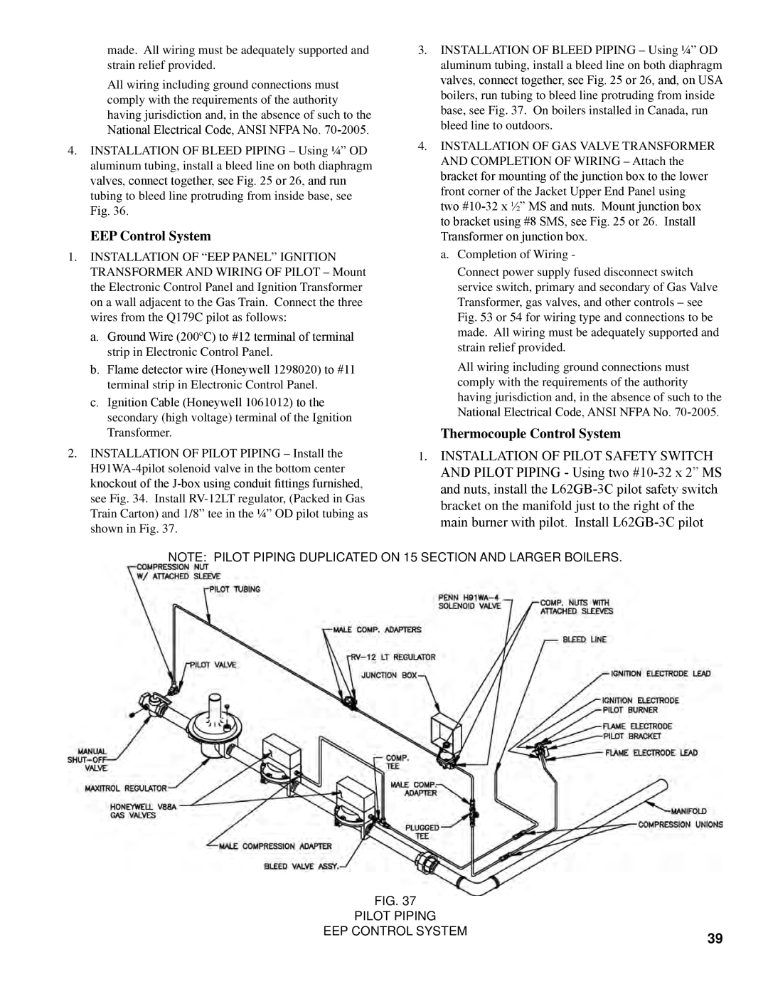
2.INSTALLATION OF PILOT PIPING – Install the
3.INSTALLATION OF BLEED PIPING – Using ¼” OD aluminum tubing, install a bleed line on both diaphragm valves, connect together, see Fig. 25 or 26, and, on USA boilers, run tubing to bleed line protruding from inside base, see Fig. 37. On boilers installed in Canada, run bleed line to outdoors.
4.INSTALLATION OF GAS VALVE TRANSFORMER AND COMPLETION OF WIRING – Attach the bracket for mounting of the junction box to the lower front corner of the Jacket Upper End Panel using two
a.Completion of Wiring -
Connect power supply fused disconnect switch service switch, primary and secondary of Gas Valve Transformer, gas valves, and other controls – see Fig. 53 or 54 for wiring type and connections to be made. All wiring must be adequately supported and strain relief provided.
All wiring including ground connections must comply with the requirements of the authority having jurisdiction and, in the absence of such to the
National Electrical Code, ANSI NFPA No.
Thermocouple Control System
1. INSTALLATION OF PILOT SAFETY SWITCH AND PILOT PIPING - Using two
Note: Pilot Piping duplicated on 15 section and larger boilers.
Fig. 37 |
|
PILOT PIPING |
|
EEP CONTROL SYSTEM | 39 |
|