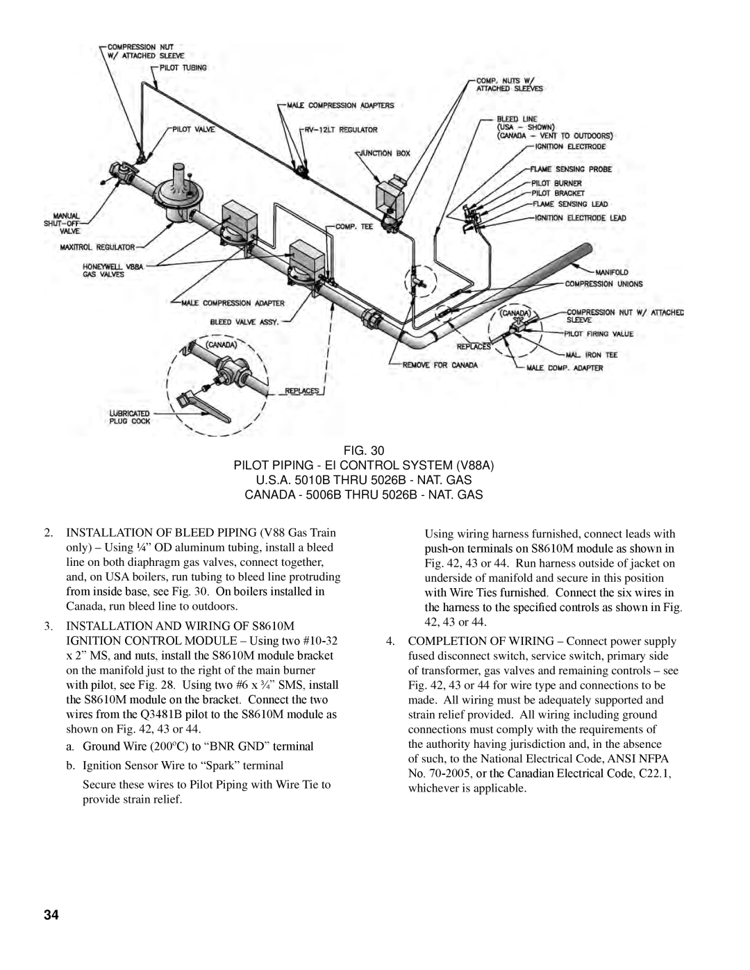
Fig. 30
PILOT PIPING - EI CONTROL SYSTEM (V88A)
U.S.A. 5010B THRU 5026B - NAT. GAS CANADA - 5006B THRU 5026B - NAT. GAS
2.INSTALLATION OF BLEED PIPING (V88 Gas Train only) – Using ¼” OD aluminum tubing, install a bleed line on both diaphragm gas valves, connect together, and, on USA boilers, run tubing to bleed line protruding from inside base, see Fig. 30. On boilers installed in
Canada, run bleed line to outdoors.
3.INSTALLATION AND WIRING OF S8610M IGNITION CONTROL MODULE – Using two
a. Ground Wire (200ºC) to “BNR GND” terminal b. Ignition Sensor Wire to “Spark” terminal
Secure these wires to Pilot Piping with Wire Tie to provide strain relief.
Using wiring harness furnished, connect leads with
4.COMPLETION OF WIRING – Connect power supply fused disconnect switch, service switch, primary side of transformer, gas valves and remaining controls – see Fig. 42, 43 or 44 for wire type and connections to be made. All wiring must be adequately supported and strain relief provided. All wiring including ground connections must comply with the requirements of the authority having jurisdiction and, in the absence of such, to the National Electrical Code, ANSI NFPA
No.
34