e.DRAW UP CENTER SECTION SLOWLY AND EVENLY, tightening each
f.KEEP
g.Using a pinch bar, insert WOOD WEDGES under last Center Section assembled so as to raise it just above Boiler Base. This will keep the next section to be assembled above the base, thus making
it easier to join and
7.ASSEMBLE REMAINING END SECTION WITH
a.After section assembly is completed install 5/8” tie rods from tie rod bundle through the upper lug holes in the front of Boiler and Lower lug holes in the rear of Boiler sections and tighten until they are finger tight only, to allow for expansion. This is necessary in order to allow clearance for installation of Flue cover plates. Finally, remove ¾”
Open Steam or Water Trim Carton
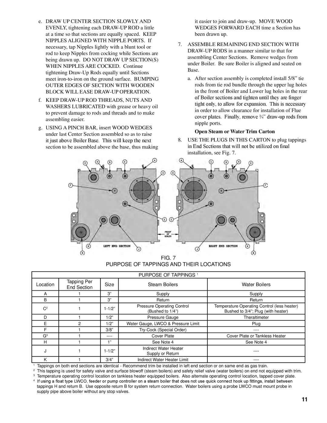
8.Use the plugs in this carton to plug tappings in End Sections that will not be utilized on final installation, see Fig. 7.
Fig. 7
PURPOSE OF TAPPINGS AND THEIR LOCATIONS
PURPOSE OF TAPPINGS 1
Location | Tapping Per | Size | Steam Boilers | Water Boilers | |
End Section | |||||
|
|
|
| ||
A | 1 | 3” | Supply | Supply | |
B | 1 | 3” | Return | Return | |
C2 | 1 | Pressure Operating Control | Temperature Operating Control (less heater) | ||
(Bushed to 1/4”) | Bushed to 3/4”; Plug (with heater) | ||||
|
|
| |||
D | 1 | 1/2” | Pressure Gauge | Theraltimeter | |
E | 2 | 1/2” | Water Gauge, LWCO & Pressure Limit | Plug | |
F | 1 | 3/8” | |||
G3 | 1 | Cover Plate | Cover Plate or Tankless Heater | ||
H | 1 | 1” | See Note 4 | See Note 4 | |
J | 1 | Indirect Water Heater | |||
Supply or Return | |||||
|
|
|
| ||
K | 1 | 3/4” | Indirect Water Heater Limit |
1Tappings on both end sections are identical - Recommend trim be installed in left end section or on same end as gas train.
2This tapping is used for safety valve and surface blowoff (steam boilers) and safety relief valve (water boilers) on end not equipped with trim.
3Temperature operating control location on tankless heater equipped boilers. Also alternate operating control location, tapped cover plate.
4If using a float type LWCO, feeder or pump controller on a steam boiler that does not use quick connect hook up fittings, install between tappings H and return B. Use opposite return B for system return connection. Water boilers using a probe LWCO must mount probe in supply pipe above boiler without any stop valves.
11