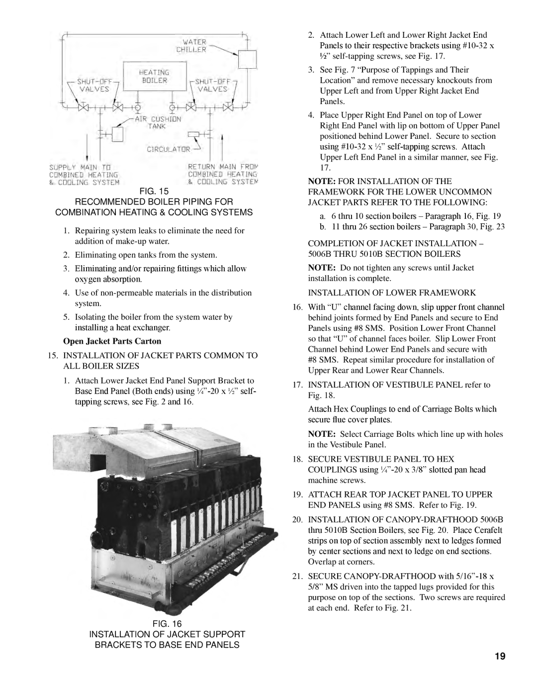
Fig. 15
RECOMMENDED BOILER PIPING FOR
COMBINATION HEATING & COOLING SYSTEMS
1.Repairing system leaks to eliminate the need for addition of
2.Eliminating open tanks from the system.
3.Eliminating and/or repairing fittings which allow oxygen absorption.
4.Use of
5.Isolating the boiler from the system water by installing a heat exchanger.
Open Jacket Parts Carton
15.INSTALLATION OF JACKET PARTS COMMON TO ALL BOILER SIZES
1.Attach Lower Jacket End Panel Support Bracket to
Base End Panel (Both ends) using
Fig. 16
INSTALLATION OF JACKET SUPPORT
BRACKETS TO BASE END PANELS
2.Attach Lower Left and Lower Right Jacket End
Panels to their respective brackets using
½”
3.See Fig. 7 “Purpose of Tappings and Their Location” and remove necessary knockouts from Upper Left and from Upper Right Jacket End Panels.
4.Place Upper Right End Panel on top of Lower Right End Panel with lip on bottom of Upper Panel positioned behind Lower Panel. Secure to section using
Upper Left End Panel in a similar manner, see Fig. 17.
NOTE: FOR INSTALLATION OF THE FRAMEWORK FOR THE LOWER UNCOMMON JACKET PARTS REFER TO THE FOLLOWING:
a.6 thru 10 section boilers – Paragraph 16, Fig. 19
b.11 thru 26 section boilers – Paragraph 30, Fig. 23
COMPLETION OF JACKET INSTALLATION – 5006B THRU 5010B SECTION BOILERS
NOTE: Do not tighten any screws until Jacket installation is complete.
INSTALLATION OF LOWER FRAMEWORK
16.With “U” channel facing down, slip upper front channel behind joints formed by End Panels and secure to End Panels using #8 SMS. Position Lower Front Channel so that “U” of channel faces boiler. Slip Lower Front Channel behind Lower End Panels and secure with
#8 SMS. Repeat similar procedure for installation of Upper Rear and Lower Rear Channels.
17.Installation of Vestibule Panel refer to Fig. 18.
Attach Hex Couplings to end of Carriage Bolts which secure flue cover plates.
NOTE: Select Carriage Bolts which line up with holes in the Vestibule Panel.
18.Secure Vestibule Panel to Hex Couplings using
19.Attach rear top Jacket Panel to Upper End Panels using #8 SMS. Refer to Fig. 19.
20.Installation of
Overlap at corners.
21.Secure
19