14.CHECK GAS INPUT RATE TO BOILER
(1)Input Rate and Maximum Inlet Pressure shown on Rating Plate must not be exceeded. Inlet pressure must not be lower than minimum inlet pressure shown on Rating Plate.
(2)All Rate checks and all adjustments are to be made while boiler is firing – all other appliances connected to the same meter as the boiler must be off.
(3)Water Manometer or water column gauge should be connected to a
(4)LP Gas Input
(a)Adjust Gas Train Regulator(s) so that manifold pressure is ten (10) inches water column.
Turning Regulator Adjusting Screw Clockwise increases pressure, Counterclockwise rotation decreases pressure. If boiler is equipped with two manifolds (5015B thru 5026B), pressure in each must be equal.
(5)Natural Gas Input
(a)Approximate Input – Adjust Gas Train
Regulator(s) so that manifold pressure is three and a half (3½) inches from water column. Turning Regulator Adjusting Screw Clockwise increases pressure, Counterclockwise rotation decreases pressure. If boiler is equipped with two manifolds, pressure in each must be equal. If more accurate check on input is necessary, see (b) below.
For minor input changes readjust Gas Train Regulator(s) to increase or decrease manifold pressure to obtain corresponding increase or decrease in gas input. If it is necessary to increase manifold pressure more than 0.3” of water to obtain rated input, remove orifices and drill one size larger. Reinstall and recheck input rate.
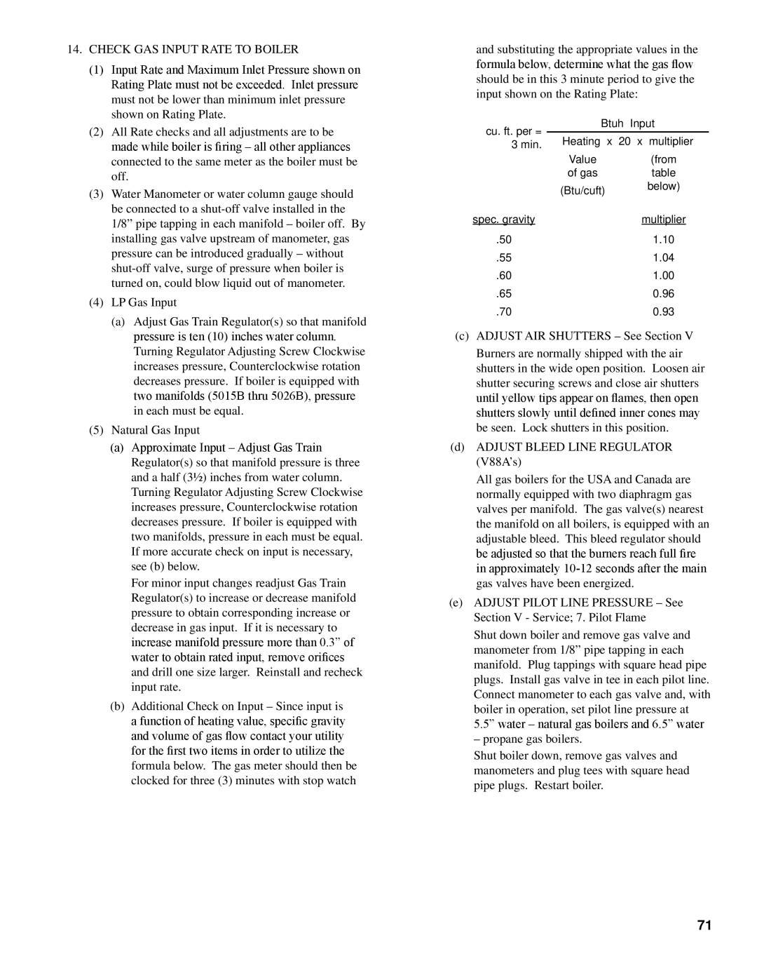
(b)Additional Check on Input – Since input is a function of heating value, specific gravity and volume of gas flow contact your utility for the first two items in order to utilize the formula below. The gas meter should then be clocked for three (3) minutes with stop watch
and substituting the appropriate values in the formula below, determine what the gas flow should be in this 3 minute period to give the input shown on the Rating Plate:
cu. ft. per = |
| Btuh Input | |
Heating |
| x 20 x multiplier | |
3 min. |
| ||
| Value |
| (from |
| of gas |
| table |
| (Btu/cuft) | below) | |
|
| ||
spec. gravity |
|
| multiplier |
.50 |
|
| 1.10 |
.55 |
|
| 1.04 |
.60 |
|
| 1.00 |
.65 |
|
| 0.96 |
.70 |
|
| 0.93 |
(c)ADJUST AIR SHUTTERS – See Section V
Burners are normally shipped with the air shutters in the wide open position. Loosen air shutter securing screws and close air shutters until yellow tips appear on flames, then open shutters slowly until defined inner cones may be seen. Lock shutters in this position.
(d)ADJUST BLEED LINE REGULATOR (V88A’s)
All gas boilers for the USA and Canada are normally equipped with two diaphragm gas valves per manifold. The gas valve(s) nearest the manifold on all boilers, is equipped with an adjustable bleed. This bleed regulator should be adjusted so that the burners reach full fire in approximately
(e)ADJUST PILOT LINE PRESSURE – See Section V - Service; 7. Pilot Flame
Shut down boiler and remove gas valve and manometer from 1/8” pipe tapping in each manifold. Plug tappings with square head pipe plugs. Install gas valve in tee in each pilot line. Connect manometer to each gas valve and, with boiler in operation, set pilot line pressure at 5.5” water – natural gas boilers and 6.5” water
– propane gas boilers.
Shut boiler down, remove gas valves and manometers and plug tees with square head pipe plugs. Restart boiler.
71