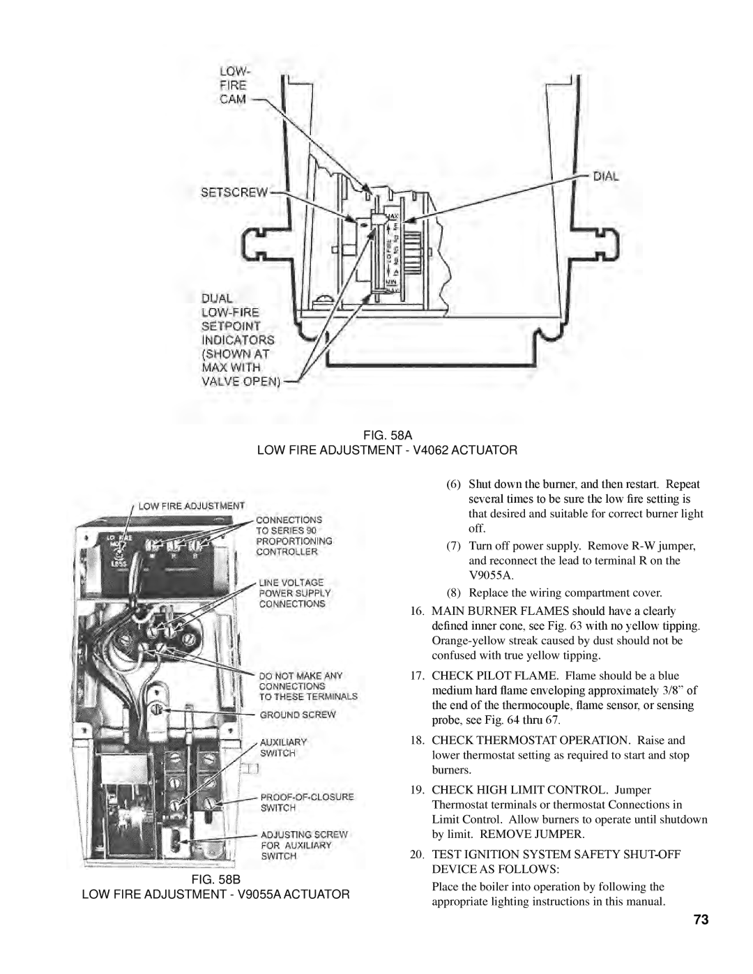
Fig. 58a
LOW FIRE ADJUSTMENT - V4062 ACTUATOR
Fig. 58B
LOW FIRE ADJUSTMENT - V9055A ACTUATOR
(6)Shut down the burner, and then restart. Repeat several times to be sure the low fire setting is that desired and suitable for correct burner light off.
(7)Turn off power supply. Remove
V9055A.
(8)Replace the wiring compartment cover.
16.MAIN BURNER FLAMES should have a clearly defined inner cone, see Fig. 63 with no yellow tipping.
17.CHECK PILOT FLAME. Flame should be a blue medium hard flame enveloping approximately 3/8” of the end of the thermocouple, flame sensor, or sensing probe, see Fig. 64 thru 67.
18.CHECK THERMOSTAT OPERATION. Raise and lower thermostat setting as required to start and stop burners.
19.CHECK HIGH LIMIT CONTROL. Jumper Thermostat terminals or thermostat Connections in Limit Control. Allow burners to operate until shutdown by limit. REMOVE JUMPER.
20.TEST IGNITION SYSTEM SAFETY SHUT-OFF
DEVICE AS FOLLOWS:
Place the boiler into operation by following the appropriate lighting instructions in this manual.
73