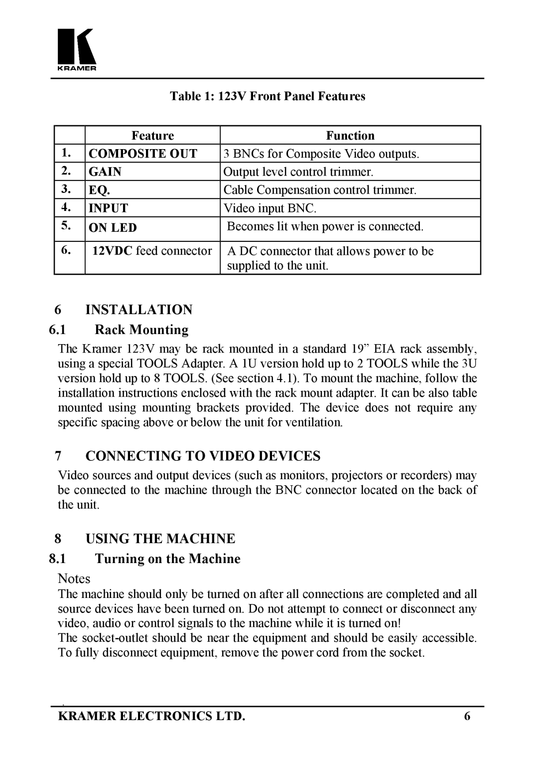
Table 1: 123V Front Panel Features
| Feature | Function |
1. | COMPOSITE OUT | 3 BNCs for Composite Video outputs. |
2. | GAIN | Output level control trimmer. |
3. | EQ. | Cable Compensation control trimmer. |
4. | INPUT | Video input BNC. |
5. | ON LED | Becomes lit when power is connected. |
|
|
|
6. | 12VDC feed connector | A DC connector that allows power to be |
|
| supplied to the unit. |
6 INSTALLATION
6.1Rack Mounting
The Kramer 123V may be rack mounted in a standard 19” EIA rack assembly, using a special TOOLS Adapter. A 1U version hold up to 2 TOOLS while the 3U version hold up to 8 TOOLS. (See section 4.1). To mount the machine, follow the installation instructions enclosed with the rack mount adapter. It can be also table mounted using mounting brackets provided. The device does not require any specific spacing above or below the unit for ventilation.
7 CONNECTING TO VIDEO DEVICES
Video sources and output devices (such as monitors, projectors or recorders) may be connected to the machine through the BNC connector located on the back of the unit.
8 USING THE MACHINE
8.1Turning on the Machine
Notes
The machine should only be turned on after all connections are completed and all source devices have been turned on. Do not attempt to connect or disconnect any video, audio or control signals to the machine while it is turned on!
The
KRAMER ELECTRONICS LTD. | 6 |
