3. — Finish installing the Pole Mount Kit
CAUTION: The PoleVault signal transmission method is specific for PVS 305SA IP switchers working with PVT wallplates. DO NOT connect the input ports to an MTP system or to an LAN or data transmission system.
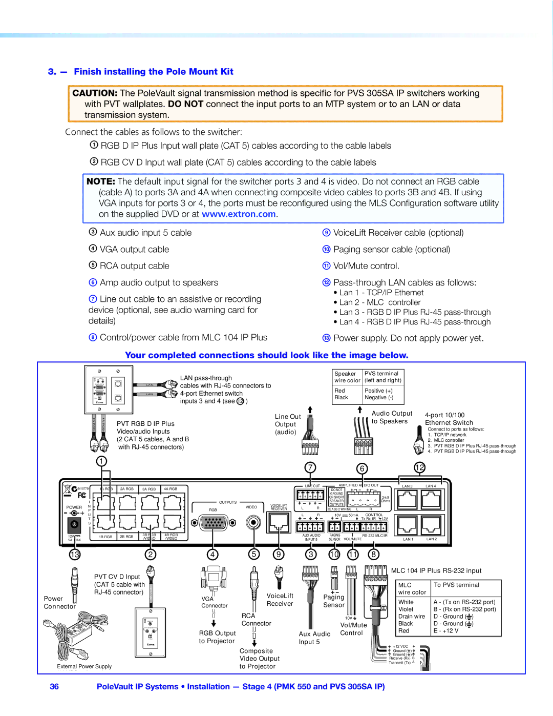
Connect the cables as follows to the switcher:
A RGB D IP Plus Input wall plate (CAT 5) cables according to the cable labels
B RGB CV D Input wall plate (CAT 5) cables according to the cable labels
NOTE: The default input signal for the switcher ports 3 and 4 is video. Do not connect an RGB cable |
(cable A) to ports 3A and 4A when connecting composite video cables to ports 3B and 4B. If using |
VGA inputs for ports 3 or 4, the ports must be reconfigured using the MLS Configuration software utility |
on the supplied DVD or at www.extron.com. |
C Aux audio input 5 cable | I VoiceLift Receiver cable (optional) |
D VGA output cable | J Paging sensor cable (optional) |
E RCA output cable | K Vol/Mute control. |
F Amp audio output to speakers | L |
G Line out cable to an assistive or recording device (optional, see audio warning card for details)
H Control/power cable from MLC 104 IP Plus
Your completed connections should look like the image below.
AUDIO
IN OUT
COMPUTER IN
MONITOR OUT
SG IR OUT![]()
1BRGB | 1ARGB |
CAT5e |
| LAN |
| LAN | cables with |
CAT5e | LAN | |
|
| inputs 3 and 4 (see 12 ) |
PVT RGB D IP Plus
Video/audio Inputs
(2 CAT 5 cables, A and B with
Line Out Output (audio)
Speaker | PVS terminal |
wire color | (left and right) |
|
|
Red | Positive (+) |
Black | Negative |
|
|
Audio Output |
| |
to Speakers | Ethernet Switch | |
| Connect to ports as follows: | |
| 1. | TCP/IP network |
| 2. | MLC controller |
| 3. | PVT RGB D IP Plus |
| 4. | PVT RGB D IP Plus |
1
7 | 6 | 12 |
![]()
![]() N15779
N15779
I
POWER N P
U
T
S
12V ![]()
![]()
![]()
5A MAX
13
1A RGB | 2A RGB | 3A RGB | 4A RGB |
|
|
|
|
1B RGB | 2B RGB | 3B RGB | 4B RGB | |
/VIDEO | /VIDEO | |||
|
|
2
| OUTPUTS | VOICELIFT | |
| VIDEO | ||
RGB | RECEIVER | ||
|
4 | 5 | 9 |
| LINE OUT | AMPLIFIED AUDIO OUT |
| |||
|
| DO NOT |
|
|
|
|
|
| GROUND |
|
|
|
|
|
| OR SHORT |
|
|
| 2/4/8 |
|
| SPEAKER |
|
|
| Ohms |
L | R | OUTPUTS |
|
|
|
|
CLASS 2 WIRING | L | R |
| |||
|
|
| ||||
L | R | 10V | 50mA | CONTROL | ||
|
|
|
|
| Tx Rx IR | 12V |
|
|
|
|
|
|
|
|
|
|
|
|
|
|
|
|
|
|
|
|
|
|
|
|
|
|
|
|
|
|
|
|
|
|
|
|
|
|
|
|
|
|
|
|
|
|
|
|
|
|
|
|
|
|
|
|
|
AUX AUDIO |
| PAGING |
|
| ||||||||||||||
INPUT 5 |
| SENSOR | VOL/MUTE | |||||||||||||||
3 10 11 8
LAN 3 | LAN 4 |
LAN 1 | LAN 2 |
PVT CV D Input |
|
(CAT 5 cable with | VIDEO |
Power | 3B |
Connector |
|
| VIDEO IN |
| AUDIO IN |
L | R |
| S G |
| IR OUT |
External Power Supply |
|
(12 VDC, 5 A max.) |
|
VGA | VoiceLift | Paging |
Connector | Receiver | Sensor |
| RCA | 10V |
| Connector | Vol/Mute |
RGB Output |
| Aux Audio Control |
to Projector |
| Input 5 |
Composite Video Output to Projector
MLC 104 IP Plus
| MLC | To PVS terminal | |||
| wire color |
|
|
| |
| White | A - (Tx on | |||
| Violet | B - (Rx on | |||
| Drain wire | D - Ground ( |
| ) | |
|
| ||||
|
| ||||
| Black | D - Ground ( |
| ) | |
| Red |
| E - +12 V | ||
|
|
|
|
|
|
+12 VDC |
|
|
|
| |
Ground ( | ) |
|
|
| |
Ground ( | ) |
|
|
| |
Receive (Rx) B
Transmit (Tx) A
36PoleVault IP Systems • Installation — Stage 4 (PMK 550 and PVS 305SA IP)