3. — Test the System |
a. Connect all the input devices (PC, DVD, |
document camera, and where desired LAN |
cables, and so forth) to the transmitters and |
power up the input devices. Check that power |
and signal are present at the transmitters. The |
LEDs light red when only power is present |
and light green when power and a signal are |
present. |
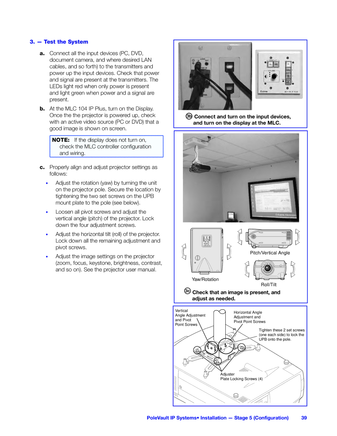
b. At the MLC 104 IP Plus, turn on the Display. |
Once the the projector is powered up, check |
with an active video source (PC or DVD) that a |
good image is shown on screen. |
NOTE: If the display does not turn on, |
check the MLC controller configuration |
and wiring. |
c. Properly align and adjust projector settings as |
follows: |
• Adjust the rotation (yaw) by turning the unit |
on the projector pole. Secure the location by |
tightening the two set screws on the UPB |
mount plate to the pole (see below). |
• Loosen all pivot screws and adjust the |
vertical angle (pitch) of the projector. Lock |
down the four adjustment screws. |
• Adjust the horizontal tilt (roll) of the projector. |
Lock down all the remaining adjustment and |
pivot screws. |
• Adjust the image settings on the projector |
(zoom, focus, keystone, brightness, contrast, |
and so on). See the projector user manual. |
ÖConnect and turn on the input devices, and turn on the display at the MLC.
Pitch/Vertical Angle
Yaw/Rotation![]() Roll/Tilt
Roll/Tilt
ÑCheck that an image is present, and adjust as needed.
Vertical | Horizontal Angle |
|
Angle Adjustment |
| |
Adjustment and |
| |
and Pivot |
| |
Pivot Point Screws |
| |
Point Screws |
| |
|
| |
| Tighten these 2 set screws | |
| (one each side) to lock the | |
| UPB onto the pole. |
|
| Adjuster |
|
| Plate Locking Screws (4) |
|
PoleVault IP Systems• Installation — Stage 5 (Configuration) | 39 | |
