4. — Install MediaLink Controller
TIP: Before cabling and installing the |
MLC 104 IP Plus, locate and write down the |
MAC address of the device for configuring the |
IP address. The 12 character alphanumeric |
address (for example, |
can be found on a label on the side of the |
controller. The length of exposed wire is critical |
to avoid transmission problems. Ensure the |
lengths given here are adhered to when strip- |
ping the cables for connection. |
NOTE: If a drain wire is used, both ends of the |
wire must be covered by heat shrink to avoid |
accidental grounding. |
a.Connect the MLC power and
| Wire Bared |
|
| 3/16" | Heat Shrink on |
| (5 mm) | Outer Jacket to |
| Max. | Inner Conductor |
|
| Transition |
Heat Shrink on |
| |
Drain Wire |
|
|
| 7/8" |
|
| (22 mm) |
|
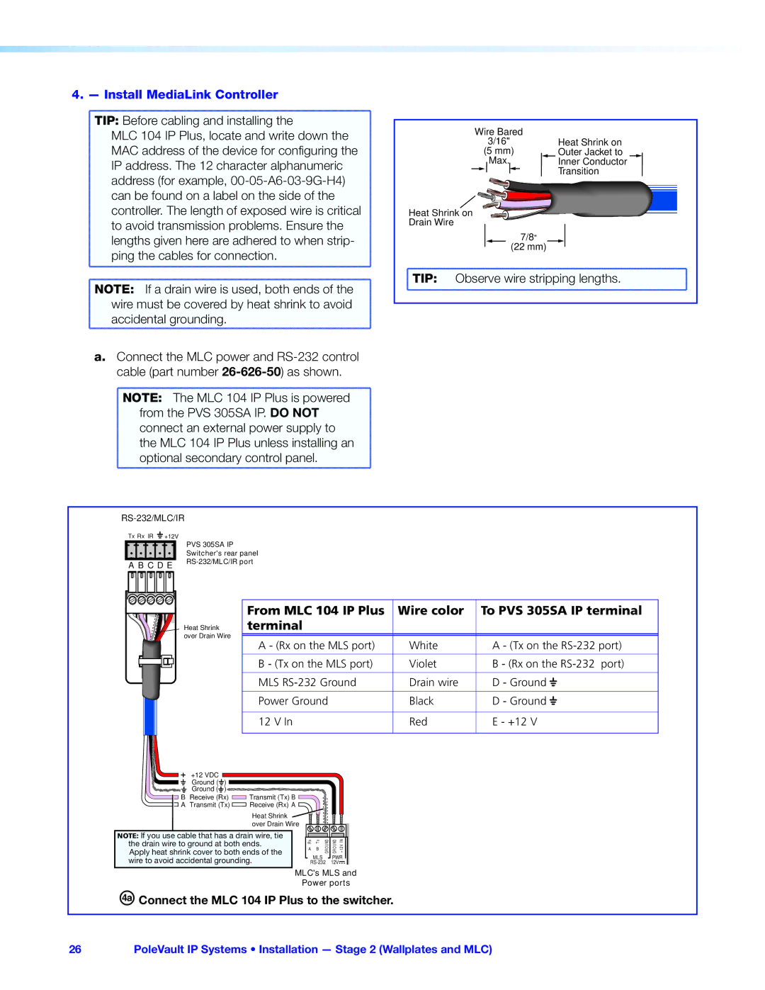
TIP: | Observe wire stripping lengths. | |
NOTE: The MLC 104 IP Plus is powered |
from the PVS 305SA IP. DO NOT |
connect an external power supply to |
the MLC 104 IP Plus unless installing an |
optional secondary control panel. |
RS-232/MLC/IR
Tx Rx IR | +12V |
A B C D E | |
PVS 305SA IP Switcher's rear panel
Heat Shrink over Drain Wire
From MLC 104 IP Plus | Wire color | To PVS 305SA IP terminal | ||
terminal |
|
|
|
|
|
|
|
|
|
A - (Rx on the MLS port) | White | A - (Tx on the | ||
|
|
|
|
|
B - (Tx on the MLS port) | Violet | B - (Rx on the | ||
|
|
|
|
|
MLS | Drain wire | D - Ground |
|
|
| ||||
|
| |||
|
|
|
|
|
Power Ground | Black | D - Ground |
|
|
| ||||
|
| |||
|
|
|
|
|
12 V In | Red | E - +12 V | ||
|
|
|
|
|
+12 VDC
Ground ( ![]() )
)
Ground (![]() )
)
BReceive (Rx) ![]() Transmit (Tx) B
Transmit (Tx) B
A Transmit (Tx) ![]() Receive (Rx) A
Receive (Rx) A
Heat Shrink |
|
|
|
|
|
over Drain Wire |
|
|
|
|
|
NOTE: If you use cable that has a drain wire, tie | Rx | Tx | GROUND | GROUND | +12VIN |
the drain wire to ground at both ends. | |||||
Apply heat shrink cover to both ends of the | A | B |
|
|
|
| MLS |
| PWR | ||
wire to avoid accidental grounding. |
|
| |||
12V |
| ||||
MLC's MLS and
Power ports
ÜConnect the MLC 104 IP Plus to the switcher.
26PoleVault IP Systems • Installation — Stage 2 (Wallplates and MLC)