2. — Pull the Cables (at the Switcher location)
a.Gather all the cables from the speakers, AV wall plates, MLC 104 IP Plus controller, and any installed optional devices that have been run to the switcher location. Pull them down through the ceiling hole and the pipe.
These cables are:
•the MLC
•the CAT 5 input cables from the wall plates
•the speaker cables
•the MLC to projector
•any optional device cables (Aux audio input Priority Page Sensor Kit, VoiceLift.)
•Ethernet cable
b.Pull the cables out of the pipe slot towards the switcher, ready for connection. Leave the
c.Connect the output video signal cables (VGA and RCA) to the switcher and pull the loose ends down the pipe so that they hang out the pipe with the
NOTE: Do not thread any high voltage |
power cabling, such as power supply |
or projector power cords, through the |
projector pipe. This violates National |
Electrical Code. |
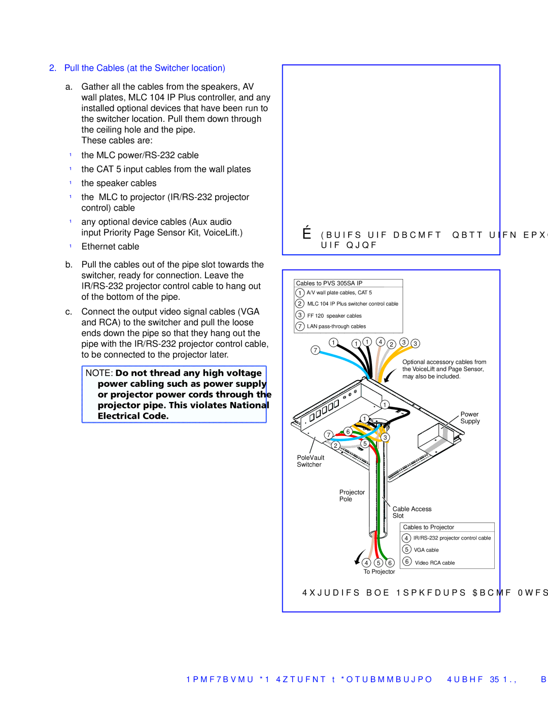
ÉGather the cables, pass them down the pipe.
Cables to PVS 305SA IP
1A/V wall plate cables, CAT 5
2MLC 104 IP Plus switcher control cable
3FF 120 speaker cables
7LAN
1 | 1 | 1 | 4 | 2 | 3 | 3 |
7 |
|
|
|
|
|
|
|
|
|
|
| Optional accessory cables from | |
|
|
|
|
| the VoiceLift and Page Sensor, | |
|
|
|
|
| may also be included. | |
|
|
|
| 1 |
|
|
|
| 1 |
|
|
| Power |
|
|
|
|
| Supply | |
|
|
|
|
|
| |
7 | 6 |
|
| 3 |
|
|
|
|
|
|
| ||
|
|
|
|
|
| |
2 | 5 |
|
PoleVault
Switcher
Projector
Pole
Cable Access
Slot
| Cables to Projector | |
| 4 | |
| 5 | VGA cable |
4 5 6 | 6 | Video RCA cable |
To Projector
Switcher and Projector Cable Overview
PoleVault IP Systems • Installation — Stage 4 (PMK 550 and PVS 305SA IP) | 35 |