CONTROLS AND CONNECTIONS
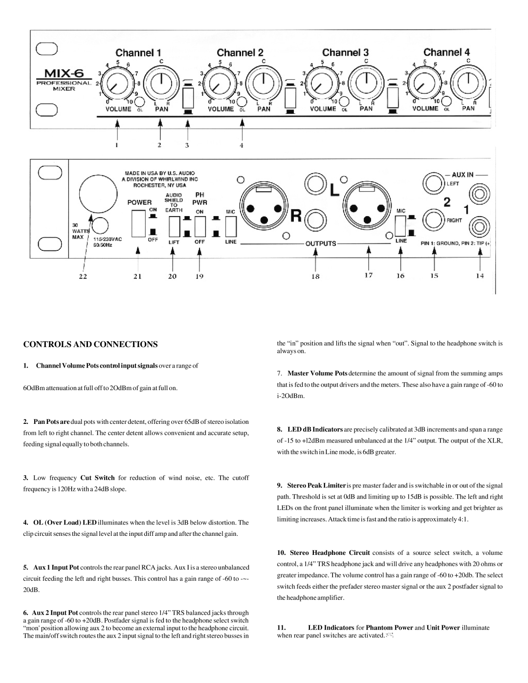
1.Channel Volume Pots control input signals over a range of
6OdBm attenuation at full off to 2OdBm of gain at full on.
2.Pan Pots are dual pots with center detent, offering over 65dB of stereo isolation from left to right channel. The center detent allows convenient and accurate setup, feeding signal equally to both channels.
3.Low frequency Cut Switch for reduction of wind noise, etc. The cutoff frequency is 120Hz with a 24dB slope.
4.OL (Over Load) LED illuminates when the level is 3dB below distortion. The clip circuit senses the signal level at the input diff amp and after the channel gain.
5.Aux 1 Input Pot controls the rear panel RCA jacks. Aux I is a stereo unbalanced circuit feeding the left and right busses. This control has a gain range of
6.Aux 2 Input Pot controls the rear panel stereo 1/4” TRS balanced jacks through a gain range of
the “in” position and lifts the signal when “out”. Signal to the headphone switch is always on.
7.Master Volume Pots determine the amount of signal from the summing amps that is fed to the output drivers and the meters. These also have a gain range of
8.LED dB Indicators are precisely calibrated at 3dB increments and span a range of
9.Stereo Peak Limiter is pre master fader and is switchable in or out of the signal path. Threshold is set at 0dB and limiting up to 15dB is possible. The left and right LEDs on the front panel illuminate when the limiter is working and get brighter as limiting increases. Attack time is fast and the ratio is approximately 4:1.
10.Stereo Headphone Circuit consists of a source select switch, a volume control, a 1/4” TRS headphone jack and will drive any headphones with 20 ohms or greater impedance. The volume control has a gain range of
11.LED Indicators for Phantom Power and Unit Power illuminate when rear panel switches are activated.![]()