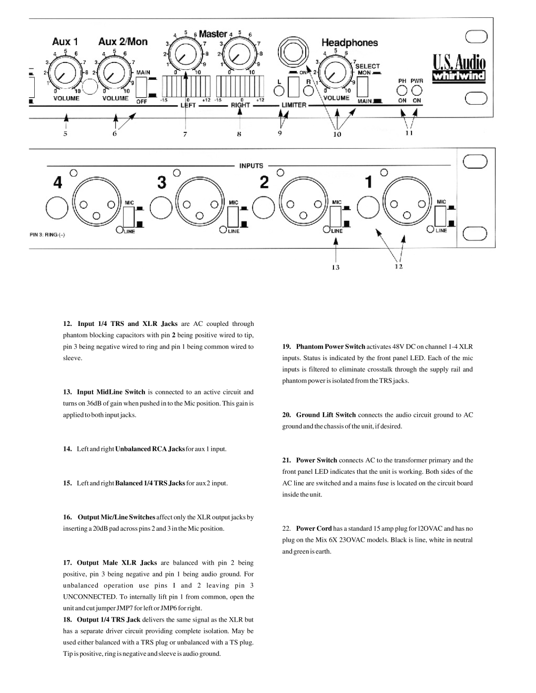
12.Input 1/4 TRS and XLR Jacks are AC coupled through phantom blocking capacitors with pin 2 being positive wired to tip, pin 3 being negative wired to ring and pin 1 being common wired to sleeve.
13.Input MidLine Switch is connected to an active circuit and turns on 36dB of gain when pushed in to the Mic position. This gain is applied to both input jacks.
14.Left and right Unbalanced RCA Jacks for aux 1 input.
15.Left and right Balanced 1/4 TRS Jacks for aux2 input.
16.Output Mic/Line Switches affect only the XLR output jacks by inserting a 20dB pad across pins 2 and 3 in the Mic position.
17.Output Male XLR Jacks are balanced with pin 2 being positive, pin 3 being negative and pin 1 being audio ground. For unbalanced operation use pins I and 2 leaving pin 3 UNCONNECTED. To internally lift pin 1 from common, open the unit and cut jumper JMP7 for left or JMP6 for right.
18.Output 1/4 TRS Jack delivers the same signal as the XLR but has a separate driver circuit providing complete isolation. May be used either balanced with a TRS plug or unbalanced with a TS plug. Tip is positive, ring is negative and sleeve is audio ground.
19.Phantom Power Switch activates 48V DC on channel
20.Ground Lift Switch connects the audio circuit ground to AC ground and the chassis of the unit, if desired.
21.Power Switch connects AC to the transformer primary and the front panel LED indicates that the unit is working. Both sides of the AC line are switched and a mains fuse is located on the circuit board inside the unit.
22.Power Cord has a standard 15 amp plug for l2OVAC and has no plug on the Mix 6X 23OVAC models. Black is line, white in neutral and green is earth.