®
W5 48 Pin MASS Connector System Technical Data - Crimp Type
The W5RP is a 48 contact addition to the virtually indestructible whirlwind Mass Connector family. This new design uses crimp type, replaceable pins and sockets. Like all Mass connectors, the W5RP has equal numbers of both pins and sockets within the resilient rubber insert. This arrangement allows two identical contact inserts to mate, requiring only a panel mount or inline housing to complete the assembly. Housings are made from machined aluminum and the
Specifications
Materials and Finishes:
![]() Contacts: Copper alloy, hard gold plate over nickel under plate per
Contacts: Copper alloy, hard gold plate over nickel under plate per
![]() Insulators: Low temperature
Insulators: Low temperature
elastomer
 "O" Rings and Seals: Low
temperature elastomer ![]() Shells and Covers: All
Shells and Covers: All
aluminum alloy, black finish,
Mechanical Data:
![]() Operating Temperature:
Operating Temperature:
![]() Contacts: #20 AWG Crimp type
Contacts: #20 AWG Crimp type
(7.5 Amp rating)
![]() Contact Retention: 20 lbs.
Contact Retention: 20 lbs.
minimum
![]() Connector Engagement and
Connector Engagement and
Separation Forces:
15 lbs. maximum
![]() Polarization: Hermaphroditic
Polarization: Hermaphroditic
Electrical Data:
![]() Operating Voltage: 500 VDC or
Operating Voltage: 500 VDC or
400 VAC rms max
Insulation Resistance: 2500
megohm minimum
Contact Resistance: 6
milliohms maximum
threaded locking ring ensures positive connection even under adverse conditions. When mating two inline connectors, one locking ring is merely unscrewed to expose threads, which are gripped by the other locking ring.
To properly mate Mass connectors, unscrew the locking rings to expose the inserts, align the inserts and push together using only hand pressure and then screw the locking ring on to secure the connection.
Due to the unique hermaphroditic design the usual connector designations of male and female do not apply, therefore Mass connectors are specified as Outputs and Inputs. An Output wired connector must mate with an Input connector configuration. The whirlwind wiring standard is odd numbered cable pairs attached to pins and even numbered cable pairs attached to sockets in the Output connector. Input wiring has odd pairs attached to sockets and even pairs attached to pins. For example, channel one is on pins in the Output connector and mates with channel one on sockets in the Input connector, which maintains color coding throughout the system. For planning system layout, whirlwind standard starts at the stage box and designates the first connector as an Output.
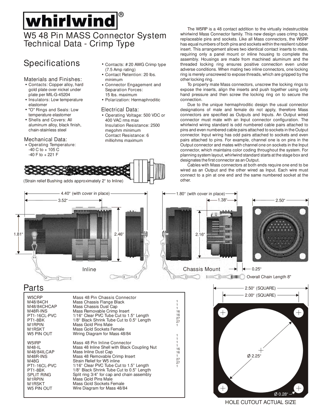
(Strain relief Bushing adds approximately 2“ to Inline)
Cables with Mass connectors at both ends require one end to be wired as an Output and the other wired as Input. Each wire must connect to a pin at one end and the same numbered socket at the other.
4.40“ (with cover in place) |
| 1.80“ (with cover in place) |
|
|
| ||||||||
3.52“ |
|
|
|
|
|
|
|
| 1.38“ |
|
| 2.50“ | |
|
|
| |||||||||||
|
|
|
|
|
|
|
|
|
|
|
|
|
|
|
|
|
|
|
|
|
|
|
|
|
|
|
|
|
|
|
|
|
|
|
|
|
|
|
|
|
|
|
|
|
|
|
|
|
|
|
|
|
|
|
|
|
|
|
|
|
|
|
|
|
|
|
|
|
|
|
|
|
|
|
|
|
|
|
|
|
|
|
|
1.81“ | 2.46“ | 2.16“ |
Inline | Chassis Mount |
![]() 0.25“
0.25“
Overall Chain Length 8"
Parts |
|
|
|
|
|
| 2.50“ (SQUARE) | |||
W5CRP | Mass 48 Pin Chassis Connector | 1 |
|
|
|
| 2.00“ (SQUARE) | |||
|
|
|
|
|
|
|
| |||
M48/84CH | Mass Chassis Flange Black |
|
|
|
|
|
|
|
| |
|
|
|
|
|
|
|
| |||
M48/84CHCAP | Mass Chassis Dust Cap | 1 |
|
|
|
|
|
|
|
|
1 |
|
|
|
|
|
|
|
| ||
Mass Removable Crimp Insert | 16 |
|
|
|
|
|
|
|
| |
|
|
|
|
|
|
|
| |||
1/16“ Clear PVC Tube Cut to 1.5“ Length | 16 |
|
|
|
|
|
|
|
| |
|
|
|
|
|
|
|
| |||
1/8“ Black Shrink Tube Cut to 0.5“ Length | 27 |
|
|
|
|
|
|
|
| |
27 |
|
|
|
|
|
|
|
| ||
M1RPIN | Mass Gold Pins Male | 1 |
|
|
|
|
|
|
|
|
M1RSKT | Mass Gold Sockets Female |
|
|
|
|
|
|
|
|
|
W5 PIN OUT | Wiring Diagram for Mass 48/84 | 1 |
|
|
|
|
|
|
|
|
|
| 1 |
|
|
|
|
|
|
|
|
W5IRP | Mass 48 Pin Inline Connector | 1 |
|
|
|
|
|
|
|
|
Mass 48 Inline Shell with Black Coupling Nut | 1 |
|
|
|
|
|
|
|
| |
16 |
|
|
|
|
|
|
|
| ||
|
|
|
|
|
|
|
| |||
M48/84ILCAP | Mass Inline Dust Cap | 16 |
|
|
|
|
|
|
|
|
|
|
|
| O 2.25“ | ||||||
Mass 48 Removable Crimp Insert | 1 |
|
|
|
| |||||
M48G | Strain Relief for W5 inline | 27 |
|
|
|
|
|
|
|
|
27 |
|
|
|
|
|
|
|
| ||
1/16“ Clear PVC Tube Cut to 1.5” Length | 1 |
|
|
|
|
|
|
|
| |
1/8“ Black Shrink Tube Cut to 0.5” Length |
|
|
|
|
|
|
|
|
| |
SPLIT RING | Split ring 3/4” for cap and chain assembly |
|
|
|
|
|
|
|
|
|
M1RPIN | Mass Gold Pins Male |
|
|
|
|
|
|
|
|
|
M1RSKT | Mass Gold Sockets Female |
|
|
|
|
|
|
|
|
|
W5 PIN OUT | Wire Diagram for Mass 48/84 |
|
|
|
|
|
|
|
|
|
|
|
|
|
|
|
|
|
| ||
O 0.28“![]()
HOLE CUTOUT ACTUAL SIZE