Input
W5 48 Pin MASS Connector System Technical Data - Crimp Type
![]() 2.75“
2.75“ ![]()
![]() 1.75“
1.75“ ![]()
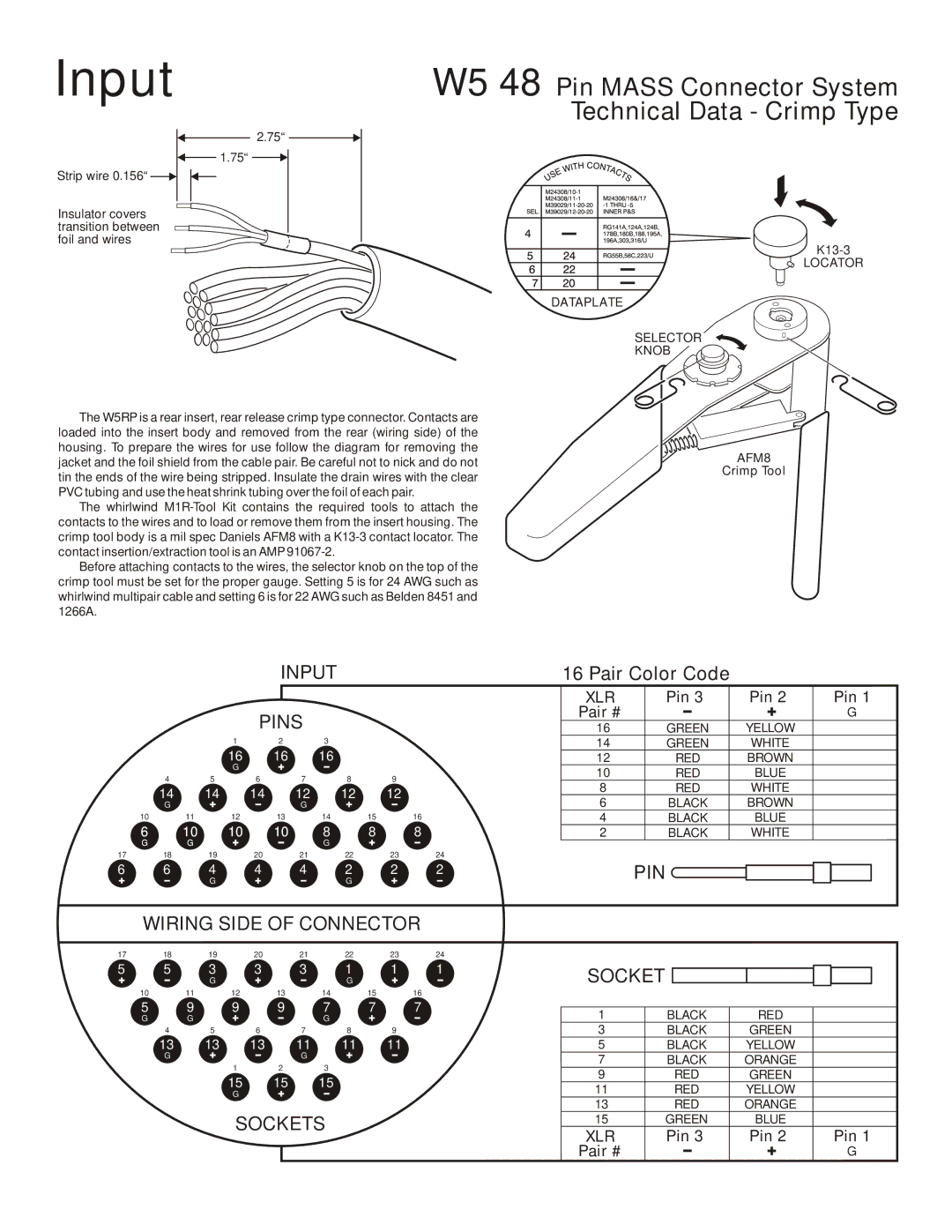
Strip wire 0.156“
Insulator covers transition between foil and wires
The W5RP is a rear insert, rear release crimp type connector. Contacts are loaded into the insert body and removed from the rear (wiring side) of the housing. To prepare the wires for use follow the diagram for removing the jacket and the foil shield from the cable pair. Be careful not to nick and do not tin the ends of the wire being stripped. Insulate the drain wires with the clear PVC tubing and use the heat shrink tubing over the foil of each pair.
The whirlwind
Before attaching contacts to the wires, the selector knob on the top of the crimp tool must be set for the proper gauge. Setting 5 is for 24 AWG such as whirlwind multipair cable and setting 6 is for 22 AWG such as Belden 8451 and 1266A.
K13-3
LOCATOR
DATAPLATE
SELECTOR
KNOB
AFM8
Crimp Tool
|
|
|
|
| INPUT |
|
|
| 16 Pair Color Code |
|
| |||
|
|
|
|
|
|
|
|
|
| XLR | Pin 3 |
| Pin 2 | Pin 1 |
|
|
|
| PINS |
|
|
|
| Pair # |
|
|
| G | |
|
|
|
|
|
|
|
| 16 | GREEN |
| YELLOW |
| ||
|
|
| 1 |
| 2 | 3 |
|
|
| 14 | GREEN |
| WHITE |
|
|
|
| 16 |
| 16 | 16 |
|
|
| 12 | RED |
| BROWN |
|
|
|
| G |
|
|
|
|
|
| 10 | RED |
| BLUE |
|
| 4 |
| 5 | 6 | 7 | 8 |
| 9 |
|
| ||||
|
|
|
| 8 | RED |
| WHITE |
| ||||||
| 14 |
| 14 | 14 | 12 | 12 |
| 12 |
|
| ||||
|
|
| 6 | BLACK |
| BROWN |
| |||||||
| G |
|
|
| G |
|
|
|
|
| ||||
| 10 | 11 | 12 |
| 13 | 14 | 15 | 16 |
| 4 | BLACK |
| BLUE |
|
| 6 | 10 | 10 |
| 10 | 8 | 8 | 8 |
| 2 | BLACK |
| WHITE |
|
| G | G |
|
|
| G |
|
|
|
|
|
|
|
|
17 | 18 |
| 19 | 20 | 21 | 22 |
| 23 | 24 |
|
|
|
|
|
6 | 6 | 4 | 4 | 4 | 2 | 272 | 2 |
|
| G |
|
| G |
|
|
PIN ![]()
WIRING SIDE OF CONNECTOR
17 18 19 20 21 22 23 24
5 | 5 | 3 | 3 | 3 | 1 | 1 | 1 | SOCKET |
|
|
|
|
| G |
|
| G |
|
|
|
|
| |
| 10 | 11 | 12 | 13 | 14 | 15 | 16 |
|
|
|
|
| 5 | 9 | 9 | 9 | 7 | 7 | 7 | 1 | BLACK | RED |
|
| G | G |
|
| G |
|
|
| |||
| 4 | 5 | 6 | 7 | 8 | 9 |
| 3 | BLACK | GREEN |
|
| 13 | 13 | 13 | 11 | 11 | 11 |
| 5 | BLACK | YELLOW |
|
| G |
|
| G |
|
|
| 7 | BLACK | ORANGE |
|
|
|
| 1 | 2 | 3 |
|
|
| |||
|
|
|
|
| 9 | RED | GREEN |
| |||
|
|
| 15 | 15 | 15 |
|
|
| |||
|
|
|
|
| 11 | RED | YELLOW |
| |||
|
|
| G |
|
|
|
|
| |||
|
|
|
|
|
|
|
| 13 | RED | ORANGE |
|
|
|
| SOCKETS |
|
| 15 | GREEN | BLUE |
| ||
|
|
|
|
| XLR | Pin 3 | Pin 2 | Pin 1 | |||
|
|
|
|
|
|
|
| ||||
|
|
|
|
|
|
|
| Pair # |
|
| G |