MAINTENANCE
MAINTENANCE
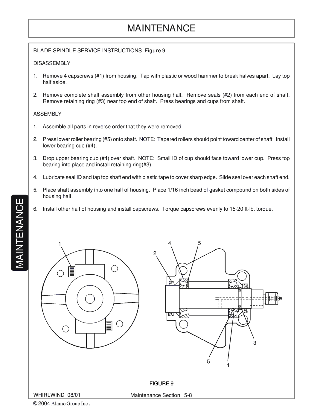
BLADE SPINDLE SERVICE INSTRUCTIONS Figure 9
DISASSEMBLY
1.Remove 4 capscrews (#1) from housing. Tap with plastic or wood hammer to break halves apart. Lay top half aside.
2.Remove complete shaft assembly from other housing half. Remove seals (#2) from each end of shaft. Remove retaining ring (#3) near top end of shaft. Press bearings and cups from shaft.
ASSEMBLY
1.Assemble all parts in reverse order that they were removed.
2.Press lower roller bearing (#5) onto shaft. NOTE: Tapered rollers should point toward center of shaft. Install lower bearing cup (#4).
3.Drop upper bearing cup (#4) over shaft. NOTE: Small ID of cup should face toward lower cup. Press top bearing into place and install retaining ring(#3).
4.Lubricate seal ID and tap top shaft end with plastic tape to cover sharp edge. Slide seal over each shaft end.
5.Place shaft assembly into one half of housing. Place 1/16 inch bead of gasket compound on both sides of housing half.
6.Install other half of housing and install capscrews. Torque capscrews evenly to
1 | 4 | 5 |
2
5
| FIGURE 9 |
WHIRLWIND 08/01 | Maintenance Section |
© 2004 Alamo Group Inc. |
|
3
4