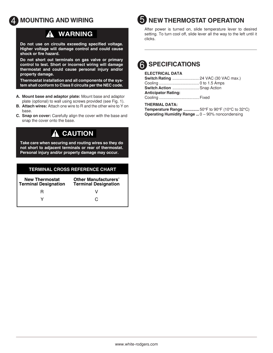
1C21 specifications
The White Rodgers 1C21 is a well-regarded thermostat designed for residential heating and cooling systems. It is known for its reliable performance and user-friendly interface. The 1C21 model offers a blend of essential features and cutting-edge technologies, making it a popular choice among homeowners looking for an efficient climate control solution.One of the key features of the White Rodgers 1C21 is its easy-to-read digital display, which allows users to monitor and adjust the temperature effortlessly. The display provides clear readouts, making it simple to ensure that the indoor environment is comfortable. Moreover, this thermostat is compatible with a variety of heating and cooling systems. It works seamlessly with gas, oil, and electric heating units, as well as central air conditioning systems, ensuring versatility for diverse home setups.
The 1C21 also incorporates a simple programming capability, allowing users to set different temperatures for different times of the day. This feature is particularly valuable for energy savings, as it enables homeowners to lower the heating or cooling when they're away or asleep, thereby reducing utility bills without sacrificing comfort.
Another notable aspect of the White Rodgers 1C21 is its user convenience. The thermostat features a straightforward installation process, typically compatible with standard wiring configurations found in most homes. Additionally, it includes intuitive buttons for easy temperature adjustments and programming, ensuring that users can operate it without the need for extensive technical knowledge.
In terms of reliability, the White Rodgers brand is known for its durable and long-lasting products. The 1C21 is designed with robust materials that can withstand the wear and tear of daily use. Furthermore, it has built-in accuracy features, maintaining consistent temperature control for optimal home comfort.
Energy efficiency is a priority for the White Rodgers 1C21, which may contribute to lower utility costs over time. By utilizing programmable settings, users can optimize their energy consumption, aligning heating and cooling needs with their daily lifestyle.
In summary, the White Rodgers 1C21 is an efficient thermostat that combines essential features, user-friendly operation, and compatibility with various heating and cooling systems. Its reliable performance and focus on energy efficiency make it a valuable addition to any home, ensuring both comfort and cost-effectiveness. Whether upgrading an old thermostat or installing a new one, the White Rodgers 1C21 is an excellent choice for maintaining a pleasant indoor climate.

