OPERATION
Before you begin programming your thermostat, you should be familiar with its features and with the display and the location and operation of the thermostat buttons. Your thermostat con- sists of two parts: the thermostat cover and the base. To remove the cover, pull it straight out from the base. To replace the cover, line up the cover with the base and press until the cover snaps onto the base.
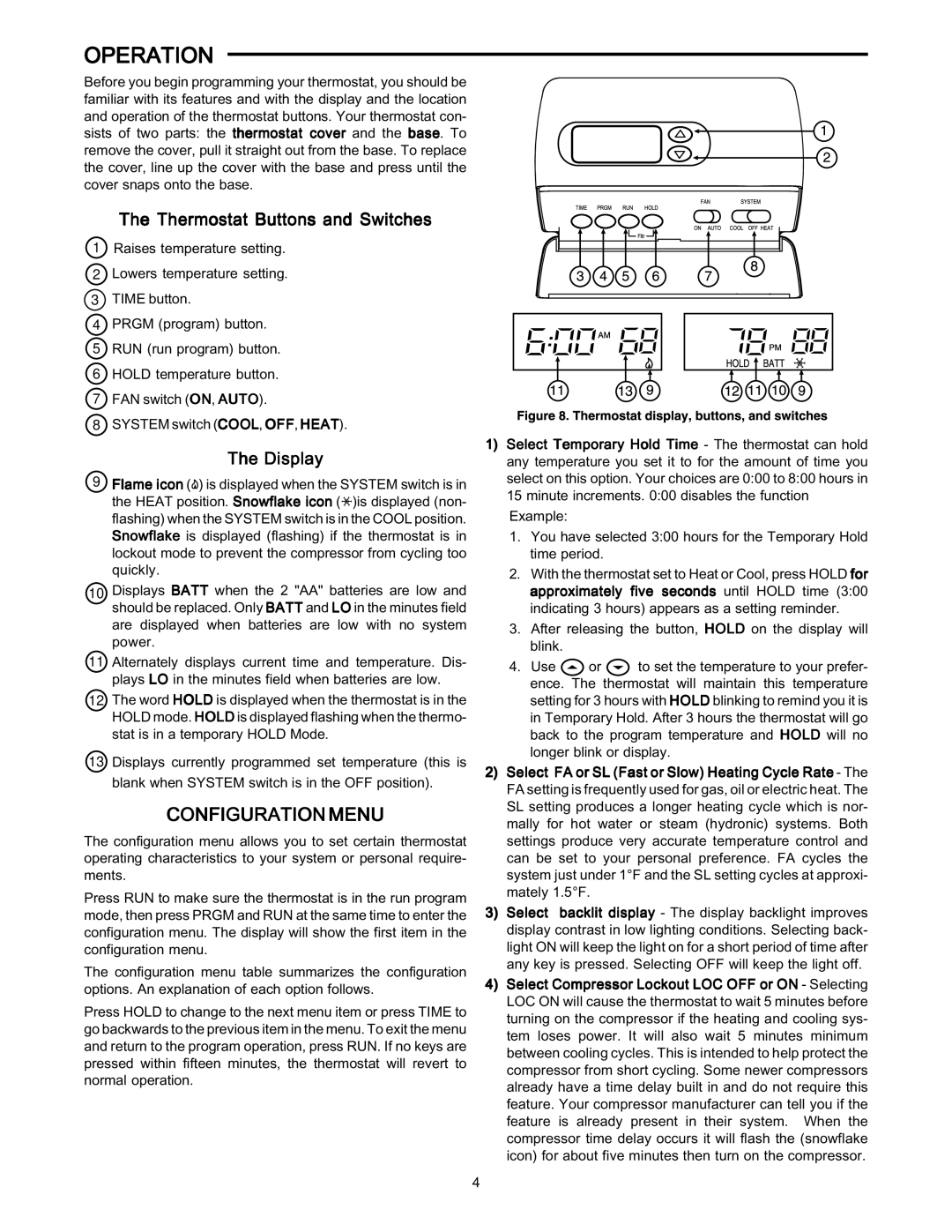
The Thermostat Buttons and Switches
1Raises temperature setting.
2Lowers temperature setting.
3TIME button.
4PRGM (program) button.
5RUN (run program) button.
6HOLD temperature button.
7FAN switch (ON, AUTO).
8SYSTEM switch (COOL, OFF, HEAT).
The Display
9Flame icon (![]() ) is displayed when the SYSTEM switch is in the HEAT position. Snowflake icon (
) is displayed when the SYSTEM switch is in the HEAT position. Snowflake icon (![]() )is displayed (non- flashing) when the SYSTEM switch is in the COOL position. Snowflake is displayed (flashing) if the thermostat is in lockout mode to prevent the compressor from cycling too quickly.
)is displayed (non- flashing) when the SYSTEM switch is in the COOL position. Snowflake is displayed (flashing) if the thermostat is in lockout mode to prevent the compressor from cycling too quickly.
10 Displays BATT when the 2 "AA" batteries are low and should be replaced. Only BATT and LO in the minutes field are displayed when batteries are low with no system power.
11 Alternately displays current time and temperature. Dis- plays LO in the minutes field when batteries are low.
12The word HOLD is displayed when the thermostat is in the HOLD mode. HOLD is displayed flashing when the thermo- stat is in a temporary HOLD Mode.
13Displays currently programmed set temperature (this is blank when SYSTEM switch is in the OFF position).
CONFIGURATION MENU
The configuration menu allows you to set certain thermostat operating characteristics to your system or personal require- ments.
Press RUN to make sure the thermostat is in the run program mode, then press PRGM and RUN at the same time to enter the configuration menu. The display will show the first item in the configuration menu.
The configuration menu table summarizes the configuration options. An explanation of each option follows.
Press HOLD to change to the next menu item or press TIME to go backwards to the previous item in the menu. To exit the menu and return to the program operation, press RUN. If no keys are pressed within fifteen minutes, the thermostat will revert to normal operation.
1)Select Temporary Hold Time - The thermostat can hold any temperature you set it to for the amount of time you select on this option. Your choices are 0:00 to 8:00 hours in 15 minute increments. 0:00 disables the function Example:
1.You have selected 3:00 hours for the Temporary Hold time period.
2.With the thermostat set to Heat or Cool, press HOLD for approximately five seconds until HOLD time (3:00 indicating 3 hours) appears as a setting reminder.
3.After releasing the button, HOLD on the display will blink.
4.Use ![]() or
or ![]() to set the temperature to your prefer- ence. The thermostat will maintain this temperature setting for 3 hours with HOLD blinking to remind you it is in Temporary Hold. After 3 hours the thermostat will go back to the program temperature and HOLD will no longer blink or display.
to set the temperature to your prefer- ence. The thermostat will maintain this temperature setting for 3 hours with HOLD blinking to remind you it is in Temporary Hold. After 3 hours the thermostat will go back to the program temperature and HOLD will no longer blink or display.
2)Select FA or SL (Fast or Slow) Heating Cycle Rate - The FA setting is frequently used for gas, oil or electric heat. The SL setting produces a longer heating cycle which is nor- mally for hot water or steam (hydronic) systems. Both settings produce very accurate temperature control and can be set to your personal preference. FA cycles the system just under 1°F and the SL setting cycles at approxi- mately 1.5°F.
3)Select backlit display - The display backlight improves display contrast in low lighting conditions. Selecting back- light ON will keep the light on for a short period of time after any key is pressed. Selecting OFF will keep the light off.
4)Select Compressor Lockout LOC OFF or ON - Selecting LOC ON will cause the thermostat to wait 5 minutes before turning on the compressor if the heating and cooling sys- tem loses power. It will also wait 5 minutes minimum between cooling cycles. This is intended to help protect the compressor from short cycling. Some newer compressors already have a time delay built in and do not require this feature. Your compressor manufacturer can tell you if the feature is already present in their system. When the compressor time delay occurs it will flash the (snowflake icon) for about five minutes then turn on the compressor.
4