1F85-277 specifications
The White Rodgers 1F85-277 is an advanced programmable thermostat known for its versatility, energy-efficiency, and user-friendly design. It stands as a reliable choice for homeowners looking to enhance their heating and cooling systems' functionality while minimizing energy consumption.One of the key features of the 1F85-277 is its 7-day programmable capability, which allows users to set schedules for different days of the week. This flexibility ensures that the home is heated or cooled according to individual preferences, thereby optimizing energy usage and providing comfort when it’s needed the most. The thermostat can program up to four different temperature settings per day, allowing precise control over home climate conditions.
Another notable characteristic of the White Rodgers 1F85-277 is its intuitive LCD display. The backlit screen is easy to read, displaying current temperature settings, scheduled programs, and system alerts clearly. This feature is especially useful during nighttime or low-light conditions. The interface allows for straightforward navigation, making it simple for users to create and modify schedules without the need for complex instructions.
The thermostat also integrates advanced technologies, including Smart Recovery. This technology ensures that the home reaches the desired temperature at the programmed time by anticipating how long it takes to heat or cool. By learning from previous system performance, it improves efficiency while maintaining home comfort.
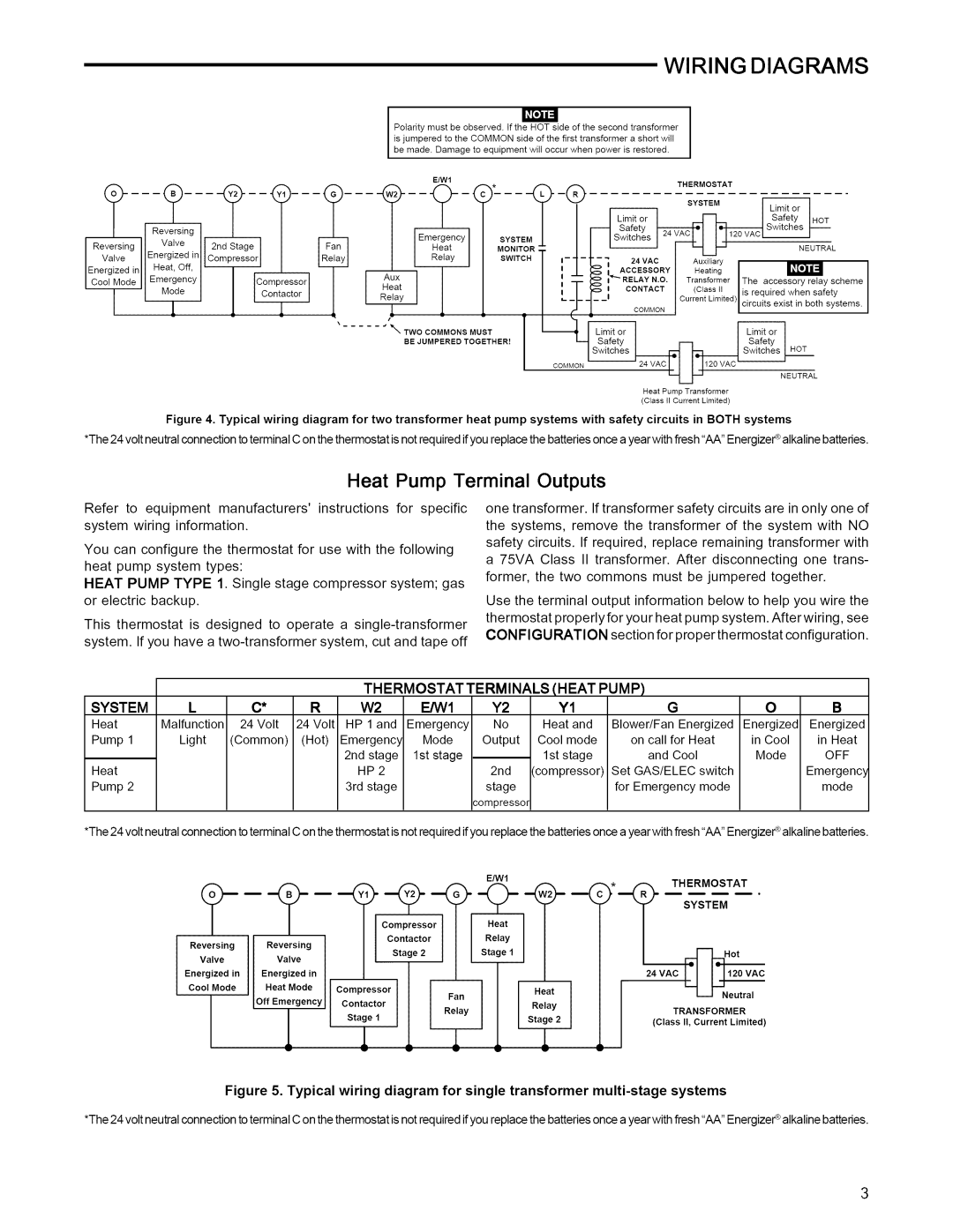
Additionally, the White Rodgers 1F85-277 is compatible with most heating and cooling systems, including gas, electric, and heat pump systems. It supports both single-stage and multi-stage heating and cooling, providing flexibility and compatibility for various home setups.
A significant advantage is its energy-saving features, which can lead to reduced utility bills. By allowing homeowners to schedule their HVAC systems more efficiently, the 1F85-277 plays a crucial role in energy conservation efforts.
Furthermore, installation is straightforward, as the thermostat is designed with a user-centric approach, allowing most homeowners to install it without professional help.
Overall, the White Rodgers 1F85-277 combines advanced technology with practical features, making it an ideal solution for those seeking to improve home comfort while managing energy costs effectively. Its programmable functionality, user-friendly interface, and compatibility with diverse heating and cooling systems make it a standout product in the thermostat market.

