WIRING DIAGRAMS

Heat Pump Connections

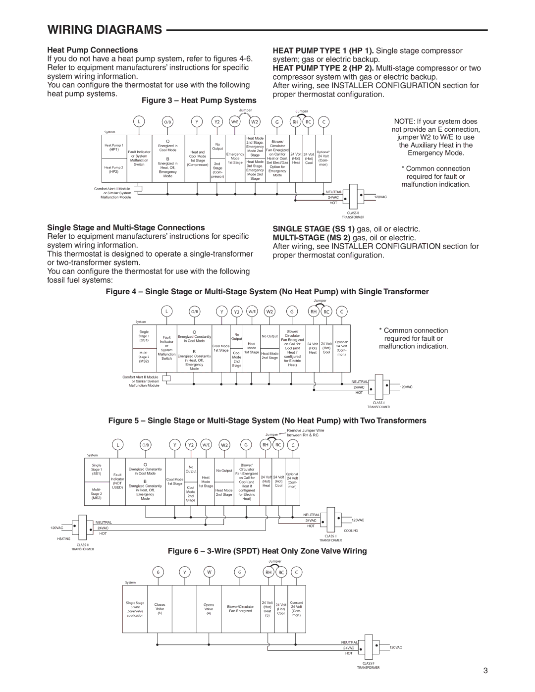
If you do not have a heat pump system, refer to fi gures 4-6. Refer to equipment manufacturers’ instructions for specifi c system wiring information.

You can confi gure the thermostat for use with the following heat pump systems.

Figure 3 – Heat Pump Systems

Jumper

HEAT PUMP TYPE 1 (HP 1). Single stage compressor system; gas or electric backup.

HEAT PUMP TYPE 2 (HP 2). Multi-stage compressor or two compressor system with gas or electric backup.

After wiring, see INSTALLER CONFIGURATION section for proper thermostat confi guration.

Jumper


L

O/B

Y

Y2

W/E

W2

G

RH

RC

C

System


O


Heat Mode

Blower/


Heat Pump 1


No


2nd Stage.


Energized in


Emergency

Circulator


Output


(HP1)

Fault Indicator

Cool Mode

Heat and


Mode 2nd

Fan Energized


Optional*


Emergency

24 Volt


or System


Cool Mode


Stage

on Call for

24 Volt

24 Volt


Malfunction

B

1st Stage


Mode


Heat or Cool.

(Hot)

(Hot)

(Com-


Heat Mode


Switch

Energized in

(Compressor)

2nd

1st Stage

Set Elect/Gas

Heat

Cool

mon)

Heat Pump 2


Heat, Off,


Stage


3rd Stage.

Option for


Emergency

Emergency


(HP2)


Emergency


(Com-


Mode 2nd

Mode


Mode


pressor)


Stage


Comfort Alert II Module

NEUTRAL

or Similar System

Malfunction Module

24VAC


HOT

NOTE: If your system does not provide an E connection, jumper W2 to W/E to use the Auxiliary Heat in the Emergency Mode.

*Common connection required for fault or

malfunction indication.

120VAC

CLASS II

TRANSFORMER

Single Stage and Multi-Stage Connections

Refer to equipment manufacturers’ instructions for specifi c system wiring information.

This thermostat is designed to operate a single-transformer or two-transformer system.

You can confi gure the thermostat for use with the following fossil fuel systems:

SINGLE STAGE (SS 1) gas, oil or electric. MULTI-STAGE (MS 2) gas, oil or electric.

After wiring, see INSTALLER CONFIGURATION section for proper thermostat confi guration.

Figure 4 – Single Stage or Multi-Stage System (No Heat Pump) with Single Transformer

Jumper


L

O/B

Y

Y2

W/E

W2

G

RH

RC

C


System


Single


O


No


Blower/


Stage 1


Fault

Energized Constantly


No Output

Circulator


Output


(SS1)


Indicator

in Cool Mode


Heat


Fan Energized

24 Volt

24 Volt

Optional*


Cool Mode


on Call for


or


Mode


Cool (and

(Hot)

(Hot)

24 Volt


System

B

1st Stage


(Com-


Multi-


Cool

1st Stage

Heat Mode

Heat if

Heat

Cool


Malfunction


mon)


Stage 2

Energized Constantly


Mode


2nd Stage

configured


Switch

in Heat, Off,


(MS2)


2nd


for Electric


Emergency


Stage


Heat)


Mode


Comfort Alert II Module


or Similar System


NEUTRAL


Malfunction Module


24VAC


HOT


*Common connection required for fault or

malfunction indication.

120VAC

CLASS II

TRANSFORMER

Figure 5 – Single Stage or Multi-Stage System (No Heat Pump) with Two Transformers


Jumper


Remove Jumper Wire


between RH & RC


L

O/B

Y

Y2

W/E

W2


G

RH

RC


C


System


Single


O


No


Blower/


Stage 1


Energized Constantly


No Output

Circulator


Output


(SS1)

Fault

in Cool Mode


Fan Energized


Optional


Heat


24 Volt

24 Volt


Indicator

B

Cool Mode


on Call for


24 Volt


Mode


Cool (and

(Hot)

(Hot)


(Com-


(NOT

1st Stage


Heat

Cool


Multi-

USED)

Energized Constantly


Cool

1st Stage

Heat Mode


Heat if


mon)


in Heat, Off,


Mode


configured


Stage 2


Emergency


2nd Stage

for Electric


2nd


(MS2)


Mode


Heat)


Stage


NEUTRAL


NEUTRAL


24VAC


120VAC


HOT


120VAC


24VAC


COOLING


HOT


HEATING


CLASS II


TRANSFORMER


CLASS II


Figure 6 – 3-Wire (SPDT) Heat Only Zone Valve Wiring


TRANSFORMER


Jumper


6


Y


W


G


RH


RC


C


System


Single Stage

3-wire

Zone Valve application

Closes

Valve

(6)

Opens

Valve

(4)

Blower/Circulator

Fan Energized

24Volt (Hot) Heat

(5)

24Volt (Hot) Cool

Constant

24Volt (Com- mon)

NEUTRAL

24VAC

120VAC

HOT

CLASS II

TRANSFORMER

3

Page 3
Image 3
White Rodgers 1F85-0471, 1F85CA-0471 Wiring Diagrams, Heat Pump Connections, Single Stage and Multi-Stage Connections

1F85CA-0471, 1F85-0471 specifications

The White Rodgers 1F85-0471 and 1F85CA-0471 are sophisticated digital thermostats designed to enhance home heating and cooling efficiency while providing user-friendly operation. These models reflect a commitment to advanced technology and ease of use, making them popular choices among homeowners seeking comfort and energy savings.

One of the main features of the 1F85 series is its touchscreen interface. The bright, clear display offers intuitive navigation, allowing users to effortlessly adjust temperature settings and program schedules. Unlike traditional thermostats, the touchscreen eliminates the complexity of buttons and knobs, making it accessible for all demographics, including those who may not be tech-savvy.

The 1F85-0471 and 1F85CA-0471 models also boast advanced programming capabilities. They provide 7-day programming options, allowing for customized heating and cooling schedules throughout the week. Homeowners can program different settings for weekdays and weekends to reduce energy consumption without sacrificing comfort. This flexibility is particularly beneficial for families with varied schedules, ensuring efficient climate control at all times.

Another technology feature is the built-in adaptive recovery function. This capability learns how long it takes to reach the desired temperature and begins the heating or cooling process early, ensuring that the home is comfortable by the scheduled time. This smart feature maximizes energy efficiency and minimizes temperature fluctuations, further enhancing comfort levels.

The 1F85 series is designed to work with virtually all HVAC systems, including gas, oil, and electric systems, making it a versatile choice for various setups. The compatibility with multi-stage systems ensures that homeowners can make the most out of their heating and cooling systems.

Among its other characteristics, the thermostat offers a real-time clock, filter change reminders, and an Energy Savings mode, which can help homeowners reduce energy costs by adjusting temperature settings during peak periods.

Overall, the White Rodgers 1F85-0471 and 1F85CA-0471 thermostats combine modern technology, flexibility, and efficiency, catering to the needs of today’s energy-conscious consumers. With their intuitive design and advanced features, these thermostats can significantly enhance the comfort of any home while promoting energy savings.