24A34 Series
Fan/Heat Sequencers
INSTALLATION INSTRUCTIONS
FAILURETO READ AND FOLLOW ALL INSTRUCTIONS CAREFULLY BEFORE INSTALLING OR OPERATING THIS CONTROL COULD CAUSE PERSONAL INJURY AND/OR PROPERTY DAMAGE.
DESCRIPTION
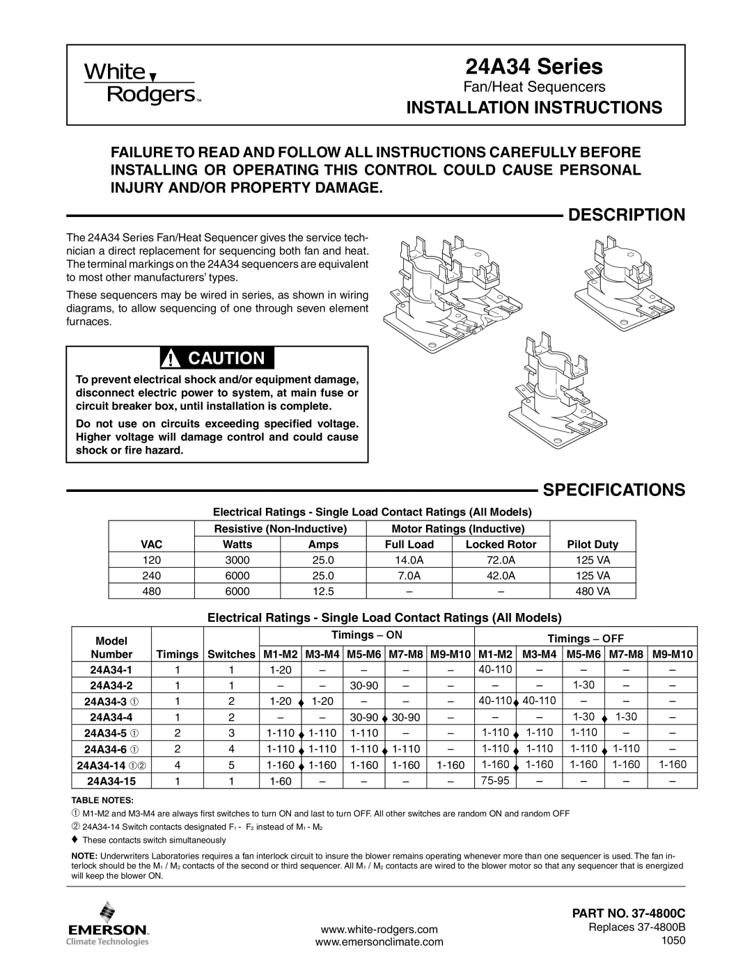
The 24A34 Series Fan/Heat Sequencer gives the service tech- nician a direct replacement for sequencing both fan and heat. The terminal markings on the 24A34 sequencers are equivalent to most other manufacturers’ types.
These sequencers may be wired in series, as shown in wiring diagrams, to allow sequencing of one through seven element furnaces.
! CAUTION
To prevent electrical shock and/or equipment damage, disconnect electric power to system, at main fuse or circuit breaker box, until installation is complete.
Do not use on circuits exceeding specified voltage. Higher voltage will damage control and could cause shock or fire hazard.
|
|
|
|
|
| SPECIFICATIONS | ||
|
| Electrical Ratings - Single Load Contact Ratings (All Models) | ||||||
|
|
|
|
| ||||
|
|
|
|
|
|
|
|
|
|
| Resistive | Motor Ratings (Inductive) |
|
|
| ||
| VAC | Watts | Amps | Full Load | Locked Rotor |
| Pilot Duty |
|
| 120 | 3000 | 25.0 | 14.0A | 72.0A |
| 125 VA |
|
| 240 | 6000 | 25.0 | 7.0A | 42.0A |
| 125 VA |
|
| 480 | 6000 | 12.5 | – | – |
| 480 VA |
|
Electrical Ratings - Single Load Contact Ratings (All Models)
Model |
|
|
| Timings – ON |
|
|
| Timings – OFF |
| ||||
Number | Timings | Switches |
| ||||||||||
1 | 1 | – | – | – | – |
| – | – | – | – | |||
1 | 1 | – | – | – | – | – |
| – | – | – | |||
1 | 2 | – | – | – | ♦ | – | – | – | |||||
1 | 2 | – | – | – | – |
| – | – | |||||
2 | 3 | – | – | ♦ | – | – | |||||||
2 | 4 | – | ♦ | – | |||||||||
4 | 5 | ♦ | |||||||||||
1 | 1 | – | – | – | – |
| – | – | – | – | |||
TABLE NOTES:
➀
➁
NOTE: Underwriters Laboratories requires a fan interlock circuit to insure the blower remains operating whenever more than one sequencer is used. The fan in- terlock should be the M1 / M2 contacts of the second or third sequencer. All M1 / M2 contacts are wired to the blower motor so that any sequencer that is energized will keep the blower ON.
| PART NO. |
Replaces | |
www.emersonclimate.com | 1050 |