36H SERIES
Combination Gas Valve
INSTALLATION INSTRUCTIONS
FAILURE TO READ AND FOLLOW ALL INSTRUCTIONS CAREFULLY BEFORE IN- STALLING OR OPERATING THIS CONTROL COULD CAUSE PERSONAL INJURY AND/OR PROPERTY DAMAGE.
DESCRIPTION
The 36H series combination gas valve is designed with redundant and main solenoid valves that control gas flow to the main burners, a pressure regulator to maintain a constant outlet pressure, and a two position on/off switch for electrical shutoff. Model numbers below include features as described:
Model | # of | Open | Proven |
No. | Stages | Characteristics | Pilot |
|
|
|
|
36H22 | 1 | Fast | NO |
36H23 | 1 | Slow | NO |
36H32 | 1 | Fast | YES |
36H33 | 1 | Slow | YES |
36H54 | 2 | Fast | NO |
36H55 | 2 | Slow | NO |
36H64 | 2 | Fast | YES |
36H65 | 2 | Slow | YES |
SPECIFICATIONS
Pressure Regulator Setting: (“ W.C.) | Type of Gas: |
| Natural Gas |
| ||||||
|
|
|
| Two Stage | Ambient Temperature: |
| ||||
| Single |
|
| Min Diff. | Pressure Rating: | 14” W.C. (1⁄2 PSI) max. | ||||
| Stage | Low | High | Low to High | Voltage: |
| 24 VAC |
| ||
| Frequency: |
| 50/60 Hz |
| ||||||
Natural Gas | 2.5 - 5.0 | 1.0 - 3.5 | 2.5 - 5.0 | 1.5 |
|
| ||||
Current: |
| Single Stage | ||||||||
LP Gas | 7.0 - 12.0 | 4.0 - 9.5 | 8.0 - 12.0 | 2.5 |
| |||||
|
| |||||||||
|
|
|
|
|
|
|
| |||
| PIPE SIZES/CAPACITIES |
|
|
|
|
| ||||
|
|
| Capacity (BTU/hr) at 1” |
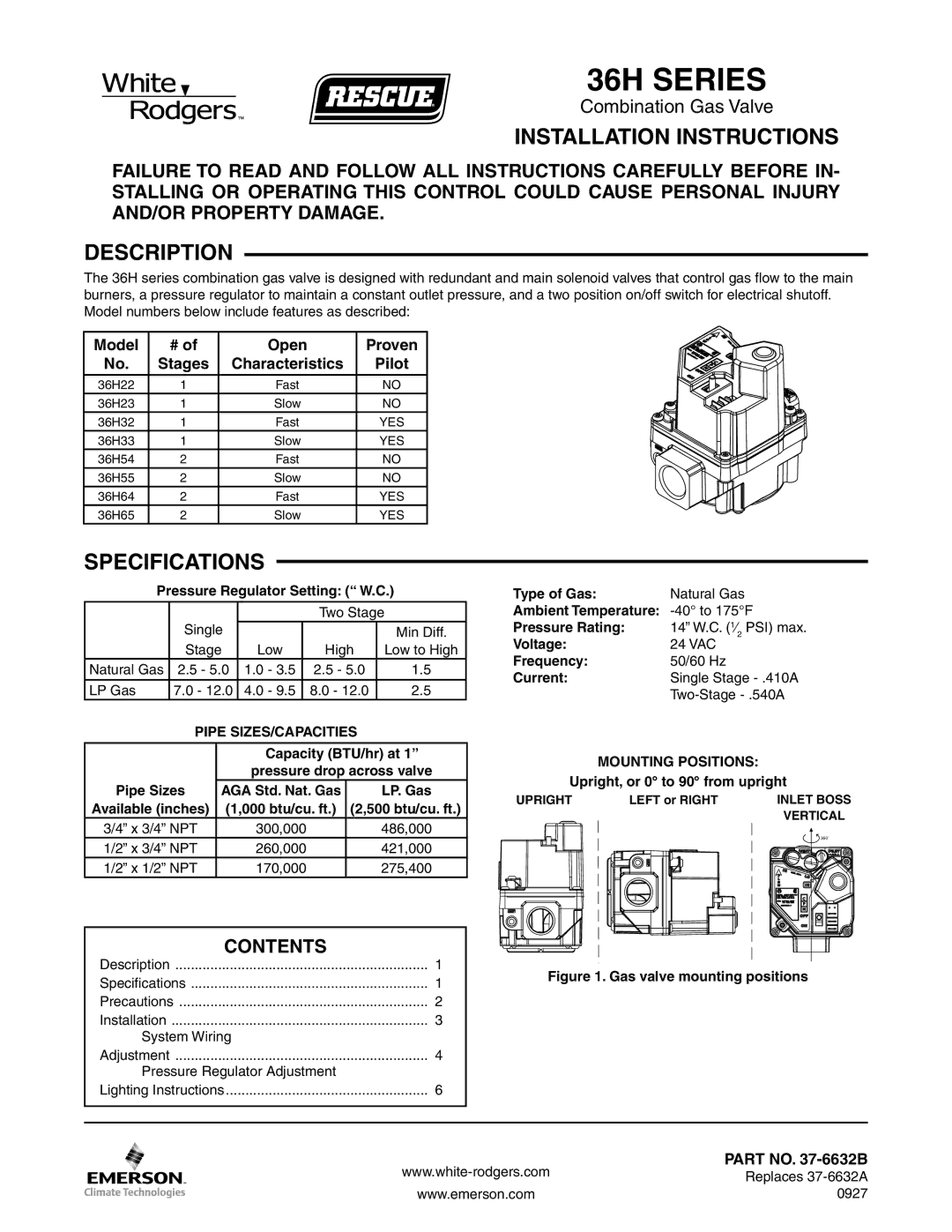
| MOUNTING POSITIONS: |
| ||||
|
|
| pressure drop across valve |
|
| |||||
|
|
| Upright, or 0° to 90° from upright | |||||||
Pipe Sizes | AGA Std. Nat. Gas | LP. Gas | ||||||||
UPRIGHT | LEFT or RIGHT | INLET BOSS | ||||||||
Available (inches) | (1,000 btu/cu. ft.) (2,500 btu/cu. ft.) | |||||||||
|
|
| VERTICAL | |||||||
3/4” x 3/4” NPT |
| 300,000 |
| 486,000 |
|
|
| |||
|
|
|
|
| 360˚ | |||||
1/2” x 3/4” NPT |
| 260,000 |
| 421,000 |
|
|
| |||
|
|
|
|
|
| |||||
1/2” x 1/2” NPT |
| 170,000 |
| 275,400 |
|
|
|
| ||
|
|
|
|
|
|
|
|
|
|
|
|
|
|
|
|
|
|
|
|
|
|
|
| CONTENTS |
|
|
|
|
|
|
|
|
|
|
|
|
|
|
|
|
|
|
|
| Description | 1 |
| Figure 1. Gas valve mounting positions | |||||||||||||||||
| Specifications | 1 |
| ||||||||||||||||||
|
|
|
|
|
|
|
|
|
|
|
|
|
|
|
|
|
|
| |||
| Precautions | 2 |
|
|
|
|
|
|
|
|
|
|
|
|
|
|
|
|
|
| |
| Installation | 3 |
|
|
|
|
|
|
|
|
|
|
|
|
|
|
|
|
|
| |
| System Wiring |
|
|
|
|
|
|
|
|
|
|
|
|
|
|
|
|
|
|
| |
| Adjustment | 4 |
|
|
|
|
|
|
|
|
|
|
|
|
|
|
|
|
|
| |
| Pressure Regulator Adjustment |
|
|
|
|
|
|
|
|
|
|
|
|
|
|
|
|
|
|
| |
| Lighting Instructions | 6 |
|
|
|
|
|
|
|
|
|
|
|
|
|
|
|
|
|
| |
|
|
|
|
|
|
|
|
|
|
|
|
|
|
|
|
|
|
|
|
|
|
|
|
|
|
|
|
|
|
|
|
|
|
|
|
|
|
|
|
|
|
|
|
|
|
|
|
|
|
|
|
|
|
|
|
|
| PART NO. | |||||||
|
|
|
|
|
|
|
|
|
|
|
|
|
|
|
| Replaces | |||||
|
|
|
|
|
|
|
|
|
|
|
|
|
|
|
|
|
|
|
|
| |
|
|
| www.emerson.com |
|
|
| 0927 | ||||||||||||||
|
|
|
|
|
| ||||||||||||||||
|
|
|
|
|
| ||||||||||||||||