INSTALLATION
SYSTEM WIRING
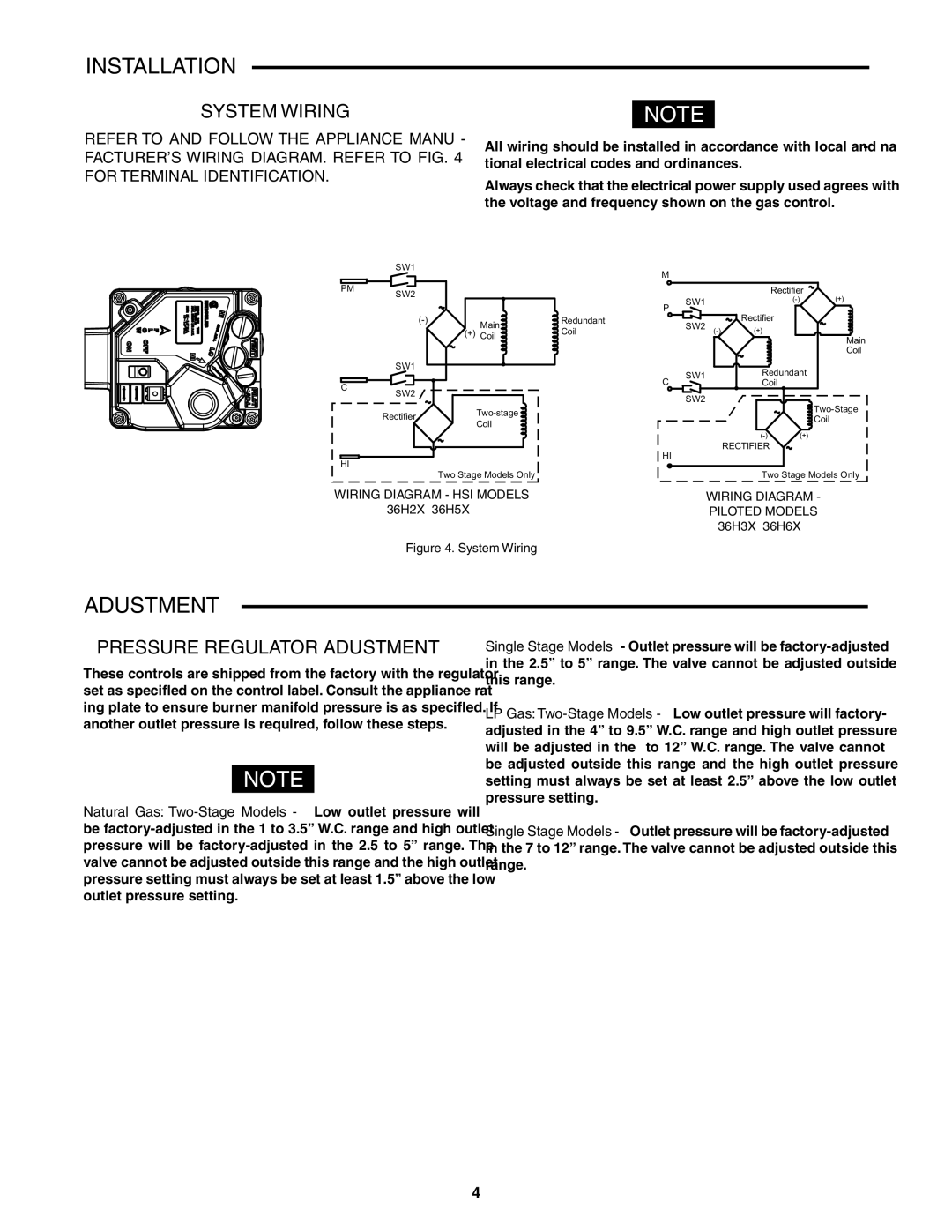
REFER TO AND FOLLOW THE APPLIANCE MANU- FACTURER’S WIRING DIAGRAM. REFER TO FIG. 4 FOR TERMINAL IDENTIFICATION.
NOTE
All wiring should be installed in accordance with local and na- tional electrical codes and ordinances.
Always check that the electrical power supply used agrees with the voltage and frequency shown on the gas control.
| SW1 |
|
|
| M |
|
|
|
|
|
|
|
|
|
|
|
|
|
|
| |
PM | SW2 |
|
|
|
|
|
| Rectifier | (+) | |
|
|
|
|
| SW1 |
|
| |||
|
|
|
|
| P |
|
| |||
|
|
|
|
|
|
| Rectifier |
|
| |
|
| Main | Redundant |
| SW2 |
|
|
| ||
|
| (+) | Coil |
| (+) |
|
| |||
|
| Coil |
|
|
|
|
| Main | ||
|
|
|
|
|
|
|
|
|
| |
|
|
|
|
|
|
|
|
|
| Coil |
| SW1 |
|
|
|
| SW1 |
| Redundant |
| |
|
|
|
|
| C |
|
| |||
|
|
|
|
|
| Coil |
|
| ||
C |
|
|
|
|
|
|
|
| ||
SW2 |
|
|
|
|
|
|
|
|
| |
|
|
|
|
| SW2 |
|
|
|
| |
|
|
|
|
|
|
|
| |||
| Rectifier |
|
|
|
|
| ||||
|
|
|
|
|
| Coil |
| |||
| Coil |
|
|
|
|
|
| |||
|
|
|
|
|
|
|
|
| ||
|
|
|
|
|
|
|
| (+) |
| |
|
|
|
|
| HI |
|
| RECTIFIER |
|
|
HI |
|
|
|
|
|
|
|
|
| |
|
|
|
|
|
|
|
|
|
| |
|
| Two Stage Models Only |
|
|
|
| Two Stage Models Only | |||
WIRING DIAGRAM - HSI MODELS |
|
| WIRING DIAGRAM - Piloted MODELS | |||||||
| 36H2X & 36H5X |
|
|
|
| WIRING DIAGRAM - |
| |||
|
|
|
|
| PILOTED MODELS |
| ||||
36H3X & 36H6X
Figure 4. System Wiring
ADJUSTMENT
PRESSURE REGULATOR ADJUSTMENT
These controls are shipped from the factory with the regulator set as specified on the control label. Consult the appliance rat- ing plate to ensure burner manifold pressure is as specified. If another outlet pressure is required, follow these steps.
NOTE
Natural Gas:
Single Stage Models- Outlet pressure will be
LP Gas:
Single Stage Models - Outlet pressure will be
4