WIRING DIAGRAMS
Heat Pump Connections
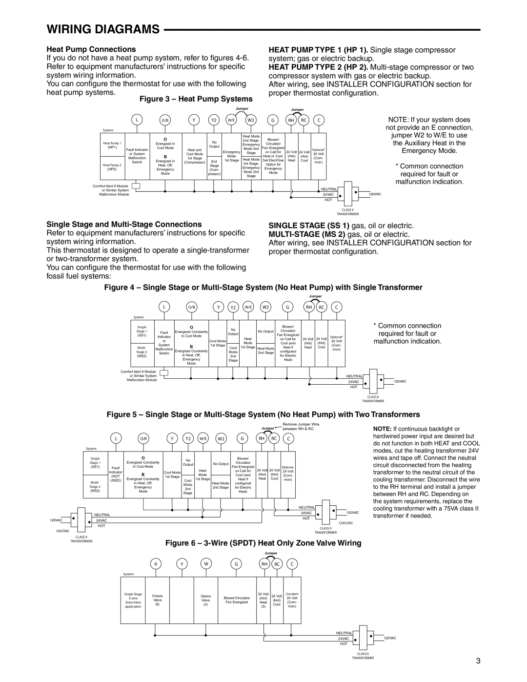
If you do not have a heat pump system, refer to figures 4-6. Refer to equipment manufacturers’ instructions for specific system wiring information.
You can configure the thermostat for use with the following heat pump systems.
Figure 3 – Heat Pump Systems

HEAT PUMP TYPE 1 (HP 1). Single stage compressor system; gas or electric backup.

HEAT PUMP TYPE 2 (HP 2). Multi-stage compressor or two compressor system with gas or electric backup.

After wiring, see INSTALLER CONFIGURATION section for proper thermostat configuration.


Jumper


Jumper


L

O/B

Y

Y2

W/E

W2

G

RH

RC

C

System


O


Heat Mode

Blower/


Heat Pump 1


No


2nd Stage.


Energized in


Emergency

Circulator


(HP1)


Output


Fault Indicator

Cool Mode

Heat and


Mode 2nd

Fan Energized


Optional*


Emergency

24 Volt


or System


Cool Mode


Stage

on Call for

24 Volt

24 Volt


Malfunction

B

1st Stage


Mode


Heat or Cool.

(Hot)

(Hot)

(Com-


Heat Mode


Switch

Energized in

(Compressor)

2nd

1st Stage

Set Elect/Gas

Heat

Cool

mon)

Heat Pump 2


Heat, Off,


Stage


3rd Stage.

Option for


(HP2)


Emergency


(Com-


Emergency

Emergency


Mode 2nd

Mode


Mode


pressor)


Stage


Comfort Alert II Module

NEUTRAL

or Similar System

Malfunction Module

24VAC


HOT

NOTE: If your system does not provide an E connection, jumper W2 to W/E to use the Auxiliary Heat in the Emergency Mode.

*Common connection required for fault or

malfunction indication.

120VAC

CLASS II

TRANSFORMER

Single Stage and Multi-Stage Connections

Refer to equipment manufacturers’ instructions for specific system wiring information.

This thermostat is designed to operate a single-transformer or two-transformer system.

You can configure the thermostat for use with the following fossil fuel systems:

Single stage (SS 1) gas, oil or electric. Multi-stage (MS 2) gas, oil or electric.

After wiring, see INSTALLER CONFIGURATION section for proper thermostat configuration.

Figure 4 – Single Stage or Multi-Stage System (No Heat Pump) with Single Transformer

Jumper


L

O/B

Y

Y2

W/E

W2

G

RH

RC

C


System


Single


O


No


Blower/


Stage 1


Fault

Energized Constantly


No Output

Circulator


Output


(SS1)

Indicator

in Cool Mode


Heat


Fan Energized

24 Volt

24 Volt

Optional*


Cool Mode


on Call for


or


Mode


Cool (and

(Hot)

(Hot)

24 Volt


System

B

1st Stage


(Com-


Multi-

Cool

1st Stage

Heat Mode

Heat if

Heat

Cool


Malfunction


mon)


Stage 2

Switch

Energized Constantly


Mode


2nd Stage

configured


in Heat, Off,


(MS2)


2nd


for Electric


Emergency


Stage


Heat)


Mode


Comfort Alert II Module


or Similar System


NEUTRAL


Malfunction Module


24VAC


HOT


*Common connection required for fault or

malfunction indication.

120VAC

CLASS II

TRANSFORMER

Figure 5 – Single Stage or Multi-Stage System (No Heat Pump) with Two Transformers


Jumper

Remove Jumper Wire


between RH & RC


L

O/B

Y

Y2

W/E

W2

G

RH

RC

C


System


Single


O


No


Blower/


Stage 1


Energized Constantly


No Output

Circulator


Output


(SS1)

Fault

in Cool Mode


Heat

Fan Energized

24 Volt

24 Volt

Optional


Indicator

B

Cool Mode


on Call for

24 Volt


(NOT

1st Stage


Mode


Cool (and

(Hot)

(Hot)

(Com-


Energized Constantly


1st Stage


Heat if

Heat

Cool

mon)


Multi-

USED)


Cool

Heat Mode


in Heat, Off,


Mode


configured


Stage 2


Emergency


2nd Stage

for Electric


2nd


(MS2)


Mode


Heat)


Stage


NEUTRAL


NEUTRAL


24VAC


120VAC


HOT


120VAC


24VAC


COOLING


HOT


HEATING


CLASS II


TRANSFORMER


CLASS II


Figure 6 – 3-Wire (SPDT) Heat Only Zone Valve Wiring


TRANSFORMER


Jumper


NOTE: If continuous backlight or hardwired power input are desired but do not function in both HEAT and COOL modes, cut the heating transformer 24V wires and tape off. Connect the neutral circuit disconnected from the heating transformer to the neutral circuit of the cooling transformer. Disconnect the wire to the RH terminal and install a jumper between RH and RC. Depending on the system requirements, replace the cooling transformer with a 75VA class II transformer if needed.

6

Y

W

G

RH RC C

System

Single Stage

3-wire

Zone Valve application

Closes

Valve

(6)

Opens

Valve

(4)

Blower/Circulator

Fan Energized

24Volt (Hot) Heat

(5)

24Volt (Hot) Cool

Constant

24Volt (Com- mon)

NEUTRAL


24VAC

120VAC

HOT


CLASS II


TRANSFORMER

3


Page 3
Image 3
White Rodgers 37-7237A specifications Single Stage and Multi-Stage Connections, Wire Spdt Heat Only Zone Valve Wiring

37-7237A specifications

The White Rodgers 37-7237A is a sophisticated thermostat designed to bring comfort and efficiency to residential heating and cooling systems. It is known for its reliability, user-friendly interface, and a variety of features that cater to the needs of modern homeowners.

One of the standout features of the 37-7237A is its digital display, which provides clear and precise temperature readings, making it easy to monitor and adjust settings. The thermostat is equipped with a simple, intuitive interface that allows for straightforward navigation through its various functions, ensuring that users can easily customize their heating and cooling preferences.

The 37-7237A supports both heat-only and cool-only systems, providing flexibility for different types of HVAC setups. It is compatible with conventional systems as well as heat pumps, making it a versatile choice for numerous household configurations. Additionally, the thermostat offers programmable capabilities, allowing users to set different temperatures for various times of the day. This feature promotes energy efficiency and helps reduce utility costs, as homeowners can lower their heating or cooling when they are not home.

Technologically, the 37-7237A incorporates advanced features such as adaptive intelligent recovery. This technology learns how long it takes to heat or cool a space to the desired temperature and begins to adjust the system's operation accordingly. As a result, the thermostat ensures that the home maintains optimal comfort without unnecessary energy expenditure.

The 37-7237A also includes a built-in temperature sensor that ensures accurate readings, helping to maintain the desired indoor climate. This consistency allows for a stable and comfortable environment, while also protecting the equipment from potential damage caused by extreme temperature fluctuations.

Another benefit of the White Rodgers 37-7237A is its energy-saving capabilities. By utilizing a programmable schedule, users can avoid heating or cooling their homes when they are not occupied. This feature can lead to significant energy savings over time.

In summary, the White Rodgers 37-7237A offers a combination of user-friendly design, advanced technology, and energy efficiency features that make it an excellent choice for homeowners seeking to enhance their indoor comfort. With its versatile compatibility and smart programming capabilities, it's an investment that pays off in both comfort and cost savings.