
50M56U-843 specifications
The White Rodgers 50M56U-843 is a versatile and reliable universal thermostat known for its innovative features and user-friendly design. This device is particularly popular among homeowners looking to optimize their HVAC systems for improved comfort and energy efficiency.One of the standout features of the 50M56U-843 is its compatibility with a wide range of heating and cooling systems. This includes conventional and heat pump systems, making it an excellent choice for various types of home environments. The thermostat supports both single-stage and multi-stage systems, allowing for comprehensive climate control tailored to specific needs.
The 50M56U-843 boasts an easy-to-read backlit display that provides clear visibility in low-light conditions. This user-friendly interface makes programming and setting adjustments straightforward, ensuring that users can quickly and easily modify settings for maximum comfort. The thermostat's simple navigation menu allows users to adjust temperatures, set schedules, and switch between heating and cooling modes with ease.
Efficiency is a key focus for the White Rodgers 50M56U-843, as it offers advanced energy-saving features. Users can take advantage of programmable settings that allow the thermostat to adjust temperatures based on daily routines, thus reducing energy consumption during times when the home is unoccupied. This feature not only saves on utility bills but also promotes environmentally friendly practices.
In terms of technological advancements, the 50M56U-843 incorporates features such as auto changeover, which allows the thermostat to automatically switch between heating and cooling modes as needed. This ensures optimal comfort without the need for constant manual adjustments. The unit also supports a wide temperature range, accommodating various climate conditions.
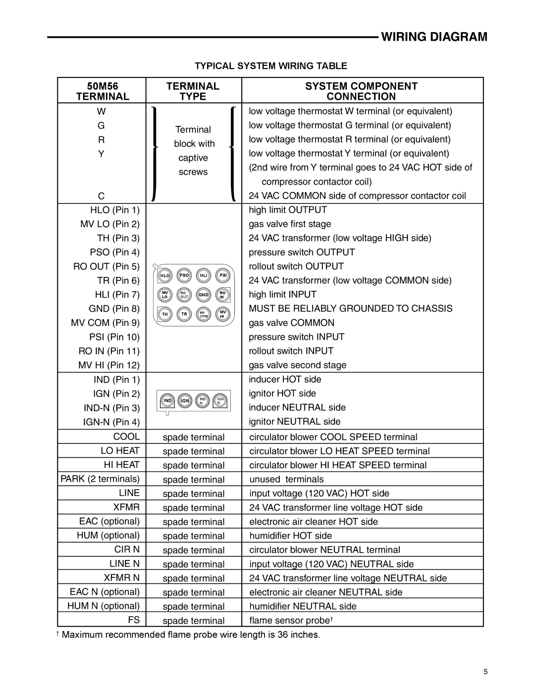
Another notable characteristic is its easy installation process. The 50M56U-843 is designed with user-friendliness in mind, providing clear instructions for mounting and wiring. This makes it feasible for homeowners to install the thermostat themselves without requiring professional assistance.
In summary, the White Rodgers 50M56U-843 is a dependable and efficient thermostat that combines functionality with user convenience. Its versatility, energy-saving features, and easy installation make it an ideal choice for those looking to enhance their home’s heating and cooling efficiency, while ensuring a comfortable living environment year-round.