INSTALLATION (CONT.)

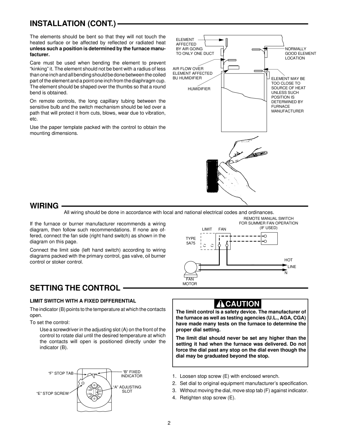
The elements should be bent so that they will not touch the heated surface or be affected by reflected or radiated heat

unless such a position is determined by the furnace manu- facturer.

Care must be used when bending the element to prevent “kinking” it. The element should not be bent with a radius of less than one inch and all bending should be done between the coiled part of the element and a point one inch from the diaphragm cup. The element should be shaped over the thumbs so that a round bend is obtained.

On remote controls, the long capillary tubing between the sensitive bulb and the switch mechanism should be led over a path that will protect it from cuts, blows, wear due to vibration, etc.

Use the paper template packed with the control to obtain the mounting dimensions.

ELEMENT

AFFECTED BY AIR GOING

TO ONLY ONE DUCT

AIR FLOW OVER ELEMENT AFFECTED BU HUMIDIFIER

HUMIDIFIER

NORMALLY GOOD ELEMENT LOCATION

ELEMENT MAY BE

TOO CLOSE TO

SOURCE OF HEAT

UNLESS SUCH

POSITION IS

DETERMINED BY

FURNACE

MANUFACTURER

WIRING

All wiring should be done in accordance with local and national electrical codes and ordinances.


REMOTE MANUAL SWITCH

If the furnace or burner manufacturer recommends a wiring


FOR SUMMER FAN OPERATION

diagram, then follow such recommendations. If none are of-


LIMIT FAN


(IF USED)


fered, connect the fan side (right hand switch) as shown in the

TYPE


diagram on this page.


5A75


Connect the limit side (left hand switch) according to wiring


diagrams packed with the primary control, gas valve, oil burner


HOT

control or stoker control.


LINE


N


FAN


SETTING THE CONTROL


MOTOR


LIMIT SWITCH WITH A FIXED DIFFERENTIAL


CAUTION


The indicator (B) points to the temperature at which the contacts


The limit control is a safety device. The manufacturer of

open.

the furnace as well as testing agencies (U.L., AGA, CGA)

To set the control:

have made many tests on the furnace to determine the

Use a screwdriver in the adjusting slot (A) on the front of the

proper dial setting.


control to rotate dial until the desired temperature at which

The limit dial should never be set any higher than the

the contacts will open is positioned directly under the

setting it had when the furnace was delivered. Do not

indicator (B).

force the dial past any stop on the dial even though the


dial may be graduated beyond the stop.


“F” STOP TAB

“B” FIXED

INDICATOR


“A” ADJUSTING

1.

Loosen stop screw (E) with enclosed wrench.

2.

Set dial to original equipment manufacturer’s specification.

“E” STOP SCREW

SLOT

3.

Without moving the dial, move stop tab (F) against indicator.

4.

Retighten stop screw (E).

2

Page 2
Image 2
White Rodgers 5A75 installation instructions Wiring, Setting the Control, Limit Switch with a Fixed Differential

5A75 specifications

The White Rodgers 5A75 is a renowned universal thermostat, specifically designed to meet the needs of both residential and commercial applications. As a product of White Rodgers, a subsidiary of Emerson Electric, the 5A75 showcases advanced technology and reliability, making it a trusted choice among HVAC professionals and homeowners alike.

One of the key features of the 5A75 thermostat is its compatibility with a wide array of heating and cooling systems. It is engineered to work seamlessly with both conventional and heat pump systems, allowing it to control gas, electric, and oil heating systems, as well as conventional and dual-fuel heat pumps. This versatility ensures that the 5A75 can cater to various setups, reducing the need for multiple thermostats across different systems.

The 5A75 comes with a user-friendly interface, featuring an easy-to-read display and simple navigation buttons. This design enables users to program their heating and cooling schedules effortlessly. Moreover, users can easily switch between heating and cooling modes, making it convenient to adapt to seasonal changes. The ability to set multiple schedules enhances energy efficiency, allowing homeowners to save on utility bills by optimizing their HVAC performance according to their lifestyle.

In terms of technology, the 5A75 utilizes digital sensing to provide precise temperature control, ensuring comfort within the desired temperature range. With an accuracy of +/- 1 degree Fahrenheit, users can enjoy consistent environmental conditions throughout their space. Additionally, the thermostat features a built-in anticipatory control that helps reduce temperature swings, further improving comfort levels.

Another notable characteristic of the White Rodgers 5A75 is its robust construction, designed to withstand the rigors of daily use. It is equipped with a reliable relay that enhances its longevity and minimizes the risk of malfunction. Furthermore, the thermostat supports easy installation, thanks to its universal mounting design and clear wiring guides.

For those concerned with energy management, the 5A75 also features a temporary override function, allowing users to adjust the temperature settings without altering the programmed schedule. This flexibility is particularly useful during unexpected weather changes or when hosting guests, ensuring comfort without sacrificing efficiency.

In conclusion, the White Rodgers 5A75 stands out as a versatile, user-friendly thermostat that combines advanced technology with reliable performance. Its compatibility with diverse HVAC systems, precise temperature control, and robust design make it a favorite for many users, contributing to comfort and energy savings in both residential and commercial environments.