_____________________________________INSTALLATION______________________________________
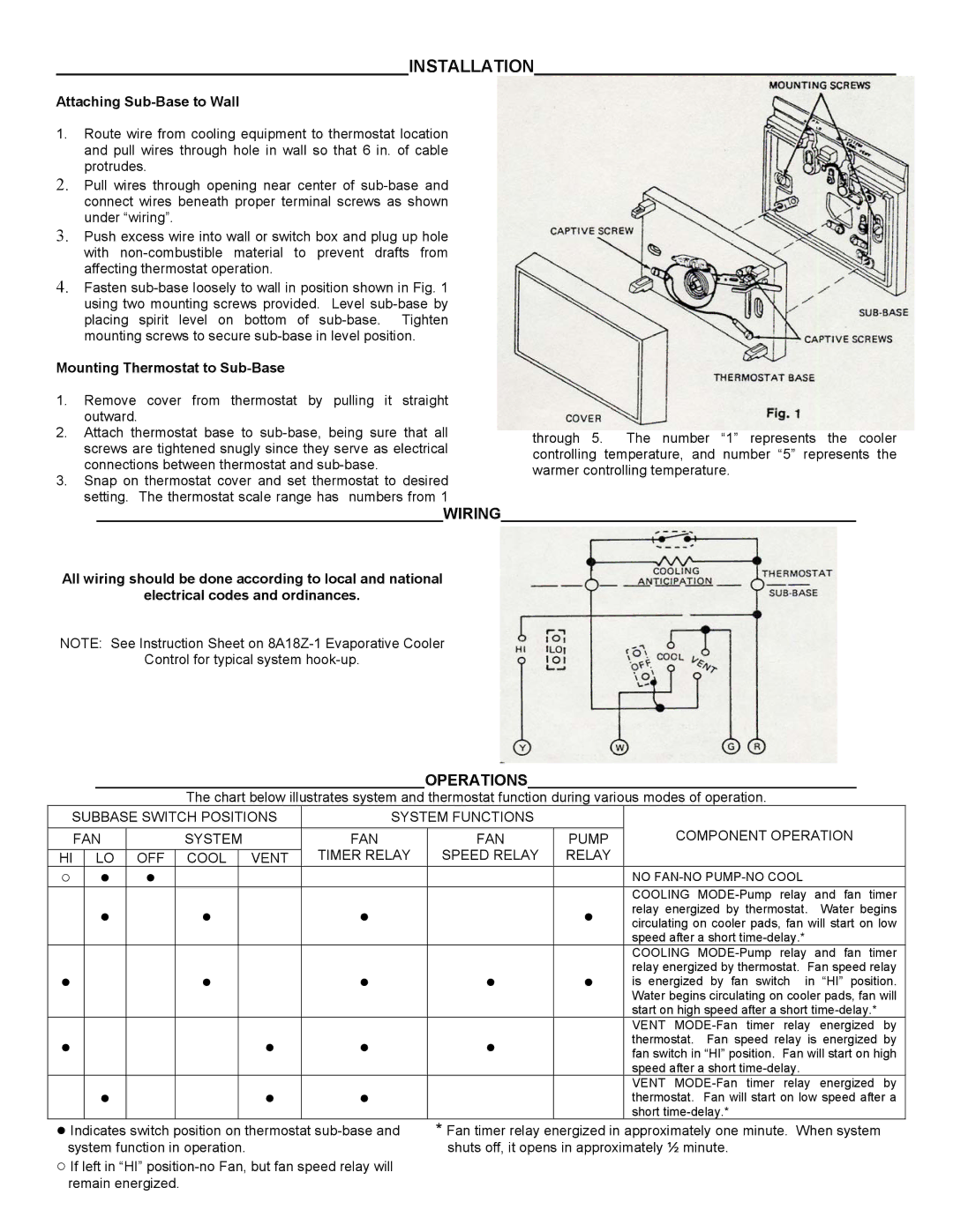
Attaching Sub-Base to Wall
1.Route wire from cooling equipment to thermostat location and pull wires through hole in wall so that 6 in. of cable protrudes.
2.Pull wires through opening near center of
3.Push excess wire into wall or switch box and plug up hole with
4.Fasten
Mounting Thermostat to Sub-Base
1.Remove cover from thermostat by pulling it straight outward.
2.Attach thermostat base to
3.Snap on thermostat cover and set thermostat to desired setting. The thermostat scale range has numbers from 1
through 5. The number “1” represents the cooler controlling temperature, and number “5” represents the warmer controlling temperature.
________________________________________WIRING_________________________________________
All wiring should be done according to local and national
electrical codes and ordinances.
NOTE: See Instruction Sheet on
Control for typical system
______________________________________OPERATIONS______________________________________
The chart below illustrates system and thermostat function during various modes of operation.
SUBBASE SWITCH POSITIONS | SYSTEM FUNCTIONS |
|
| ||||||
| FAN |
| SYSTEM | FAN | FAN | PUMP | COMPONENT OPERATION | ||
|
|
|
|
|
| TIMER RELAY | SPEED RELAY | RELAY |
|
HI |
| LO | OFF | COOL | VENT |
| |||
○ |
| ● | ● |
|
|
|
|
| NO |
|
|
|
|
|
|
|
|
| COOLING |
|
| ● |
| ● |
| ● |
| ● | relay energized by thermostat. Water begins |
|
|
|
|
| circulating on cooler pads, fan will start on low | ||||
|
|
|
|
|
|
|
|
| speed after a short |
|
|
|
|
|
|
|
|
| COOLING |
● |
|
|
| ● |
| ● | ● | ● | relay energized by thermostat. Fan speed relay |
|
|
|
| is energized by fan switch in “HI” position. | |||||
|
|
|
|
|
|
|
|
| Water begins circulating on cooler pads, fan will |
|
|
|
|
|
|
|
|
| start on high speed after a short |
|
|
|
|
|
|
|
|
| VENT |
● |
|
|
|
| ● | ● | ● |
| thermostat. Fan speed relay is energized by |
|
|
|
|
| fan switch in “HI” position. Fan will start on high | ||||
|
|
|
|
|
|
|
|
| speed after a short |
|
| ● |
|
| ● | ● |
|
| VENT |
|
|
|
|
|
| thermostat. Fan will start on low speed after a | |||
|
|
|
|
|
|
|
|
| short |
●Indicates switch position on thermostat
○If left in “HI”
*Fan timer relay energized in approximately one minute. When system shuts off, it opens in approximately ½ minute.