5. Select an appropriate location for mounting the con- |
trol. Position the case on a smooth flat surface in a |
vertical position only (with electrical knockouts down). |
INSTALLATION (cont’d)
All wiring should be done in accordance with local and national electrical codes and ordinances.
Mount the case using flat washers and screws (not |
provided) through the four mounting holes in the back |
of the case. |
NOTE
Install conduit, then run wiring and install the thermostat according to thermostat installation instructions (included with thermostat) before installing panel assembly in case.
!CAUTION
![]() N 120V
N 120V
HOT
GND![]()
PUMP MOTOR
(120 V)
L0
COM
HI
(120 V)
120 VAC DIAGRAM
R W Y G
|
|
|
|
|
N 120V | L2 240V |
| R | |
P2 120V | P2 240V |
|
| |
|
|
| PUMP | W |
F2 120V | F2 | 240V |
| |
RELAY |
| |||
|
|
| FAN SPEED | Y |
L1 | P1 |
|
| |
PUMP | RELAY |
| ||
|
|
| ||
|
|
|
| |
|
| RELAY |
| G |
L0 |
|
| FAN TIMER | |
|
| RELAY |
| |
LO SPEED |
|
| ||
|
|
| ||
FAN |
| FAN |
|
|
HI |
|
|
| |
| TIMER |
|
| |
HI SPEED |
|
| ||
RELAY |
|
| ||
FAN |
|
|
| |
|
|
| INTERNAL WIRING | |
|
|
| FIELD INSTALLED WIRING | |
|
|
| ELECTRICAL CONNECTION | |
grounding of control.
6.After wiring is run into case, bend the wires out slightly so that the wires will be in front of the panel assembly when it is installed.
7.Loosen the three panel mounting screws in the case approximately one turn. Slide the two slots located at the top of the panel assembly under the two mounting screws at the top of the case. Lower the panel assem- bly into the case until the bottom mounting screw protrudes through the keyhole slot on the panel. Slide the panel assembly up toward the top of the case, then hold the panel assembly in place while tightening all three mounting screws.
L2 ![]()
240V HOT
L1 HOT
GND![]()
PUMP MOTOR
(240 V)
L0
COM
HI
(240 V)
240 VAC DIAGRAM
R W Y G
|
|
|
| |
N 120V | L2 240V |
| R | |
P2 120V | P2 240V |
|
| |
|
|
| PUMP | W |
F2 120V | F2 | 240V |
| |
RELAY |
| |||
|
|
|
| |
|
|
| FAN SPEED | Y |
L1 | P1 |
|
| |
PUMP | RELAY |
| ||
|
|
| ||
|
|
|
| |
|
| RELAY |
| G |
L0 |
|
| FAN TIMER | |
|
| RELAY |
| |
LO SPEED |
|
| ||
|
|
| ||
FAN |
| FAN |
|
|
HI |
|
|
| |
| TIMER |
|
| |
HI SPEED RELAY |
|
| ||
FAN |
|
|
| |
|
|
| INTERNAL WIRING | |
|
|
| FIELD INSTALLED WIRING | |
|
|
| ELECTRICAL CONNECTION | |
!CAUTION
Do not over tighten panel mounting screws to avoid damage to the panel assembly.
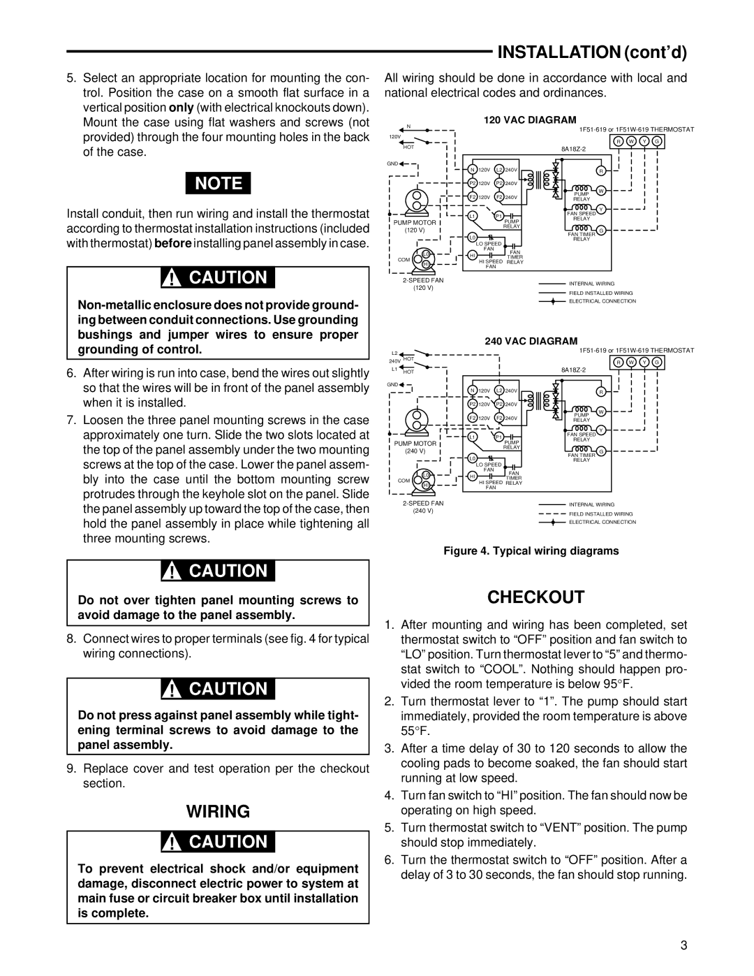
8.Connect wires to proper terminals (see fig. 4 for typical wiring connections).
!CAUTION
Do not press against panel assembly while tight- ening terminal screws to avoid damage to the panel assembly.
9.Replace cover and test operation per the checkout section.
WIRING
!CAUTION
To prevent electrical shock and/or equipment damage, disconnect electric power to system at main fuse or circuit breaker box until installation is complete.
Figure 4. Typical wiring diagrams
CHECKOUT
1.After mounting and wiring has been completed, set thermostat switch to “OFF” position and fan switch to “LO” position. Turn thermostat lever to “5” and thermo-
stat switch to “COOL”. Nothing should happen pro- vided the room temperature is below 95°F.
2.Turn thermostat lever to “1”. The pump should start
immediately, provided the room temperature is above 55°F.
3.After a time delay of 30 to 120 seconds to allow the cooling pads to become soaked, the fan should start running at low speed.
4.Turn fan switch to “HI” position. The fan should now be operating on high speed.
5.Turn thermostat switch to “VENT” position. The pump should stop immediately.
6.Turn the thermostat switch to “OFF” position. After a delay of 3 to 30 seconds, the fan should stop running.
3