SPECIFICATIONS
Electrical Ratings:
Input Voltage: 120 or 240 VAC, 60 Hz.
Operating Ambient Temperature Range:
40to 150°F (5 to 65°C)
Power Consumption:
6Watts nominal with all three relays energized
Fan Rating:
12FLA., 72 LRA; 120 VAC
6FLA., 36 LRA; 240 VAC
Pump Rating:
10FLA., 60 LRA: 120 VAC
5FLA., 30 LRA; 240 VAC
Combined Total Connected Load:
16 FLA., 120 VAC
8 FLA., 240 VAC
Mounting:
Four 9⁄32” Dia. holes
(2 1⁄2” x 5” center line to center line)
Dimensions:
6” wide x 8” high x 3” deep
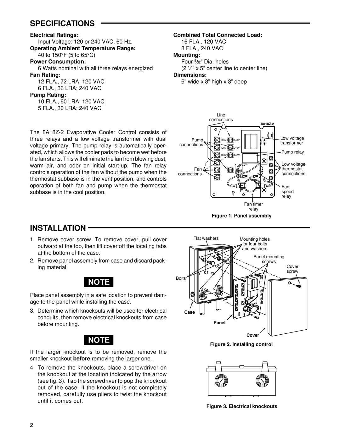
Line
connections
The
Pump connections ![]()
Fan ![]() connections
connections ![]()
N 120V L2 240V
P2 120V P2 240V
F2 120V F2 240V
L1
LO P1
HI
| Low voltage | |
| transformer | |
| Pump relay | |
R |
| |
W | Low voltage | |
Y | thermostat | |
connections | ||
| ||
G |
| |
| Fan | |
| speed | |
| relay | |
Fan timer |
| |
relay |
|
Figure 1. Panel assembly
INSTALLATION
1.Remove cover screw. To remove cover, pull cover outward at the top, then lift cover off the locating tabs at the bottom of the case.
2.Remove panel assembly from case and discard pack- ing material.
NOTE
Place panel assembly in a safe location to prevent dam- age to the panel while installing the case.
3.Determine which knockouts will be used for electrical conduits, then remove electrical knockouts from case before mounting.
NOTE
If the larger knockout is to be removed, remove the smaller knockout before removing the larger one.
4.To remove the knockouts, place a screwdriver on the knockout at the location indicated by the arrow (see fig. 3). Tap the screwdriver to pop the knockout out of the case. If the knockout is not completely removed, carefully use pliers to twist the knockout until it comes out.
Flat washers | Mounting holes |
| for four bolts |
| and washers |
| Panel mounting |
| screws |
Cover screw
Bolts
Case
Panel
Cover
Figure 2. Installing control
Figure 3. Electrical knockouts
2