WIRING DIAGRAMS
S1 S2 S3 |
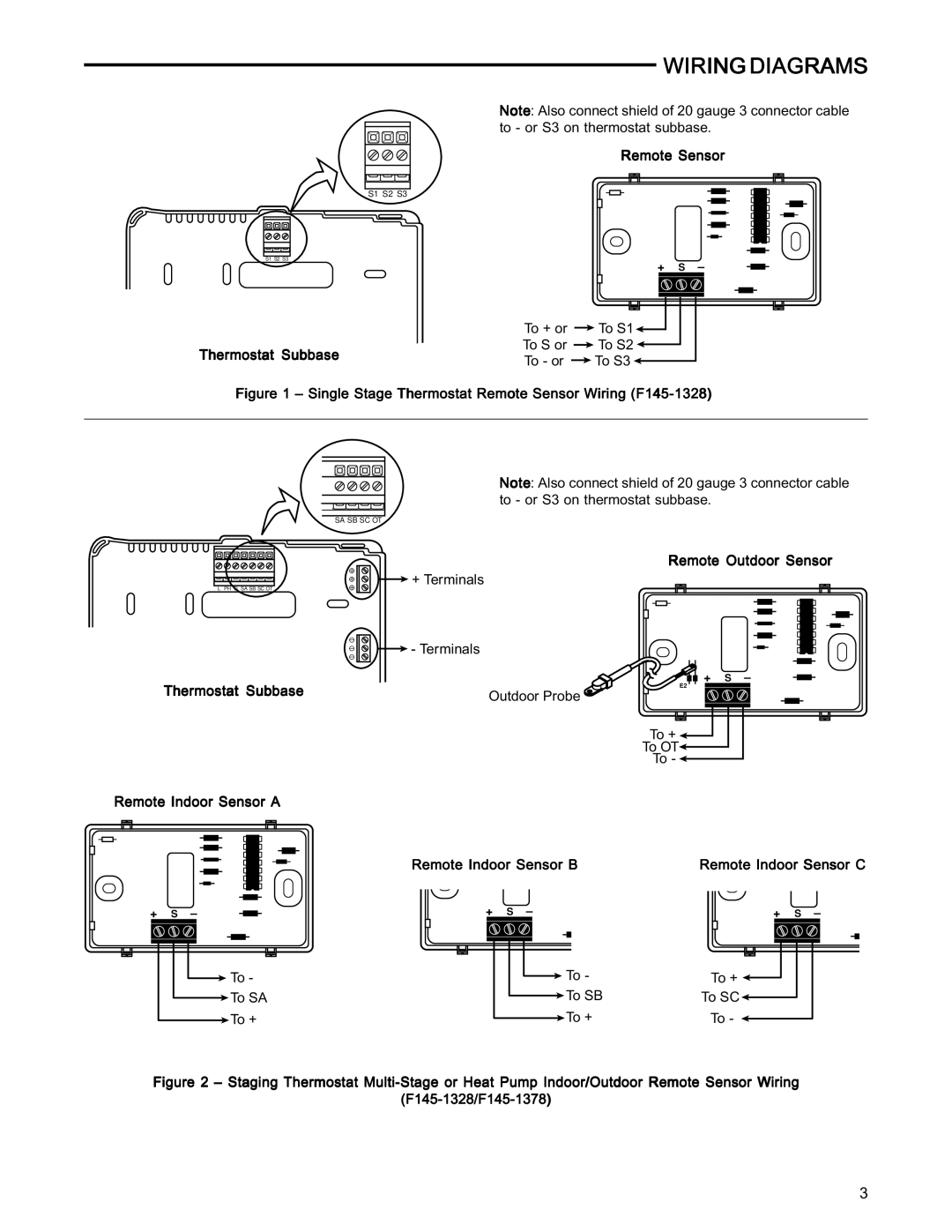
Note: Also connect shield of 20 gauge 3 connector cable to - or S3 on thermostat subbase.
Remote Sensor
S1 S2 S3 |
+ S –
|
| E2 | |
| To + or | To S1 | |
Thermostat Subbase | To S or | To S2 | |
To - or | To S3 | ||
|
Figure 1 – Single Stage Thermostat Remote Sensor Wiring (F145-1328)
Note: Also connect shield of 20 gauge 3 connector cable to - or S3 on thermostat subbase.
SA SB SC OT
L PH D SA SB SC OT |
Remote Outdoor Sensor
![]() + Terminals
+ Terminals
![]() - Terminals
- Terminals
Thermostat Subbase | Outdoor Probe |
|
E2
+ S –
To + ![]()
![]()
To OT![]()
To - ![]()
Remote Indoor Sensor A
Remote Indoor Sensor B | Remote Indoor Sensor C |
+ | S | – | + | S | – | + | S | – |
E2 |
|
| E2 |
|
| E2 |
|
|
To - |
|
|
| To - | To + | ||
| |||||||
To SA |
|
|
|
| To SB | To SC | |
|
|
| |||||
To + |
|
|
|
| To + | To - | |
|
|
|
| ||||
Figure 2 – Staging Thermostat Multi-Stage or Heat Pump Indoor/Outdoor Remote Sensor Wiring
(F145-1328/F145-1378)
3
