Manuals
/
White Rodgers
/
Household Appliance
/
Furnace
White Rodgers
G1N 4R9
manual
Electrical Connection, Wood Only, Wood/Electric
Models:
G1N 4R9
1
9
31
31
Download
31 pages
5.55 Kb
6
7
8
9
10
11
12
13
Troubleshooting
Specification
Install
Warranty
Maintenance
20 KW @ 30KW COMMAND
Pipe Connector And Damper
Replacement Parts
Safety
Switch
Page 9
Image 9
Page 8
Page 10
Page 9
Image 9
Page 8
Page 10
Contents
QuébecQuébec G1N 4R9
Stove Builder International Inc 1700, Léon-Harmel
WOOD
COMBINED ELECTRIC
Table of contents
11. TROUBLESHOOTING
LIMITED LIFETIME WARRANTY
12. DUCTS AND REGISTER MEASUREMENTS
INTRODUCTION
2. SAFETY RULES
1.CHIMNEY AND DRAFT
GENERAL REQUIREMENTS
THEASH DRAWER GET VERY HOT
W A R N I N G
DONOT MANIPULATE WITH BARE HANDS
ODOUR FROM THE PAINT
The drawer must be cleaned regularly
3. APPLIANCE INSTALLATION
SMOKE DETECTOR
ASH DRAWER
CLEARANCES TO COMBUSTIBLE MATERIALS
PIPE CONNECTOR AND DAMPER
24” both sides for PSG5000
WOOD FLUE PIPE
UNPROPER INSTALLATION
PROPER INSTALLATION
DAMPER
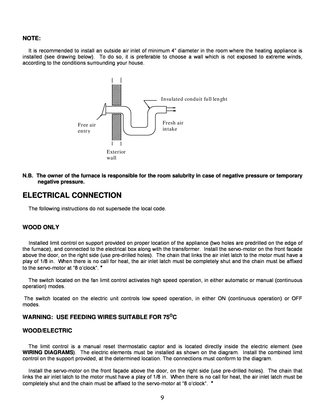
COMBUSTION AIR
ELECTRICAL CONNECTION
WARNING USE FEEDING WIRES SUITABLE FOR 75OC
WOOD ONLY
WOOD/ELECTRIC
WARNING USE FEEDING WIRES SUITABLE FOR 75OC
Red button manual reset Thermodisk L-170
ELECTRIC ELEMENT
INSIDE VIEW OF THE ELECTRIC ELEMENT
THERMOSTAT
FAN CONTROL
OUTSIDE VIEW OF THE ELECTRIC ELEMENT
Control system
4. OPERATING INSTRUCTIONS
LIGHTING
PREHEATING
except for lighting and maintenance
PROCEDURE TO OPEN THE LOADING DOOR
HEATING
EARLY SIGNS OF OVERFIRED FURNACE
LOCAL FIRE DEPARTMENT
CHIMNEY FIRES
MAINTENANCE OF THE EXCHANGERS
5. MAINTENANCE
MAINTENANCE OF THE BLOWER MOTOR
CHIMNEY MAINTENANCE
DOOR GASKET MAINTENANCE
6. REPLACEMENT PARTS
FILTERS
GASKET
WOOD-ONLYFURNACES
7. ELECTRIC DIAGRAMS FOR UNITS BUILT FROM
THERMINAL
BOARD
15 KW @ 30KW
WOOD/ELECTRIC FURNACES
BLOWER
PSG5000 WOOD-ONLYFURNACES
2 SPEED
MOTOR
PSG5000 WOOD/ELECTRIC FURNACES
20 KW @ 30KW
20 KW @ 30KW
SWITCH
8. ELECTRIC DIAGRAMS FOR UNITS BUILT BEFORE
WOOD ONLY FURNACES PSG
BLOWER
BLOWER
WOOD ONLY FURNACES PSG
MOTOR
1 SPEED
15 KW @ 30KW
WOOD/ELECTRIC FURNACES PSG
20 KW @ 30KW COMMAND
WOOD/ELECTRIC FURNACES PSG 5000 40KW @ 60KW
20 KW @ 30KW
BOARD
TERMINAL
WOOD ONLY FURNACES PSG
BLOWER
15 KW @ 30KW
WOOD/ELECTRIC FURNACES PSG
9. TECHNICAL SPECIFICATIONS
COMMERCIAL AREA
RESIDENTIAL AREA
IMPORTANT NOTE
11. TROUBLESHOOTING
DAMPER
12. DUCTS AND REGISTER MEASUREMENTS
Exposed walls
N.B. The main duct must
WARRANTY APPLICATION
LIMITED LIFETIME WARRANTY
1700, rue Léon-Harmel,Québec Québec G1N 4R9
tel. 418 527-3060fax
Top
Page
Image
Contents