THE COMFORT PRODUCTS PEOPLE

DIRECT-VENT PROPANE/LP GAS HEATER

INSTALLATION

(Continued)

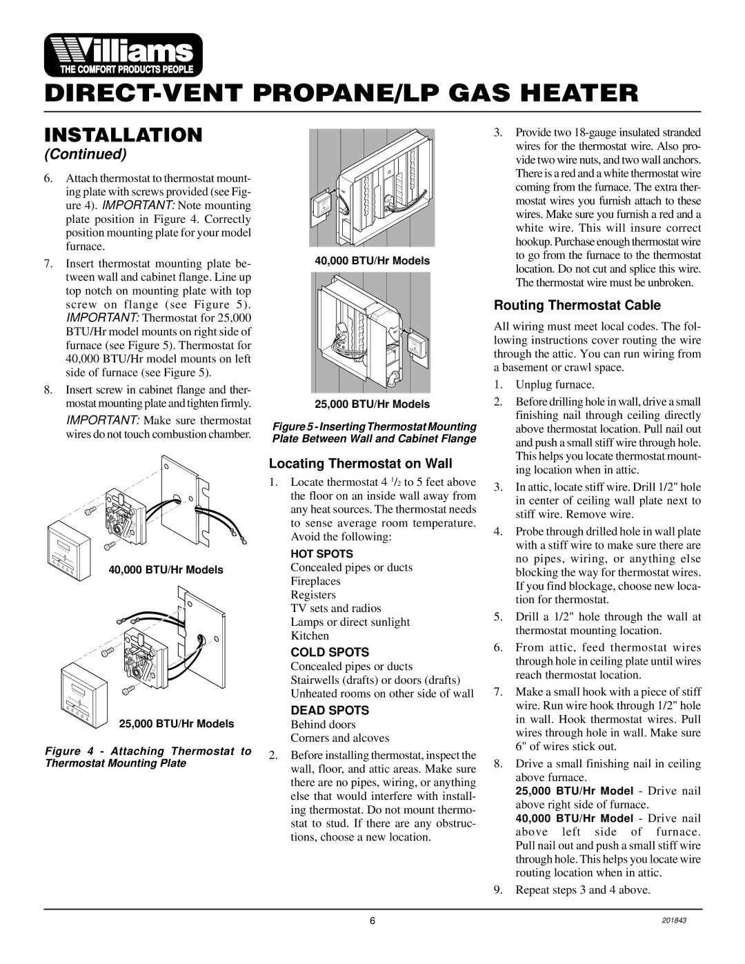
6.Attach thermostat to thermostat mount- ing plate with screws provided (see Fig- ure 4). IMPORTANT: Note mounting plate position in Figure 4. Correctly position mounting plate for your model furnace.

7.Insert thermostat mounting plate be- tween wall and cabinet flange. Line up top notch on mounting plate with top screw on flange (see Figure 5). IMPORTANT: Thermostat for 25,000 BTU/Hr model mounts on right side of furnace (see Figure 5). Thermostat for 40,000 BTU/Hr model mounts on left side of furnace (see Figure 5).

8.Insert screw in cabinet flange and ther- mostat mounting plate and tighten firmly.

IMPORTANT: Make sure thermostat wires do not touch combustion chamber.


.2


.3


.4

OFF

.5


.7


1.0


50

60


70


SOLID


80

90


STATE


50

60


IGNITION

40,000 BTU/Hr Models


70


90


80


.2


.3


.4

OFF

.5


.7


1.0


50

60


70

80


SOLID


90


STATE


50

60


IGNITION


70


80


90

25,000 BTU/Hr Models


Figure 4 - Attaching Thermostat to Thermostat Mounting Plate


00

00


00

00


00


40,000 BTU/Hr Models

50

60


70

80


90

25,000 BTU/Hr Models

Figure 5 - Inserting Thermostat Mounting Plate Between Wall and Cabinet Flange

Locating Thermostat on Wall

1.Locate thermostat 4 1/2 to 5 feet above the floor on an inside wall away from any heat sources. The thermostat needs to sense average room temperature. Avoid the following:

HOT SPOTS

Concealed pipes or ducts Fireplaces

Registers

TV sets and radios Lamps or direct sunlight Kitchen

COLD SPOTS

Concealed pipes or ducts Stairwells (drafts) or doors (drafts) Unheated rooms on other side of wall

DEAD SPOTS

Behind doors Corners and alcoves

2.Before installing thermostat, inspect the wall, floor, and attic areas. Make sure there are no pipes, wiring, or anything else that would interfere with install- ing thermostat. Do not mount thermo- stat to stud. If there are any obstruc- tions, choose a new location.

3.Provide two 18-gauge insulated stranded wires for the thermostat wire. Also pro- vide two wire nuts, and two wall anchors. There is a red and a white thermostat wire coming from the furnace. The extra ther- mostat wires you furnish attach to these wires. Make sure you furnish a red and a white wire. This will insure correct hookup. Purchase enough thermostat wire to go from the furnace to the thermostat location. Do not cut and splice this wire. The thermostat wire must be unbroken.

Routing Thermostat Cable

All wiring must meet local codes. The fol- lowing instructions cover routing the wire through the attic. You can run wiring from a basement or crawl space.

1.Unplug furnace.

2.Before drilling hole in wall, drive a small finishing nail through ceiling directly above thermostat location. Pull nail out and push a small stiff wire through hole. This helps you locate thermostat mount- ing location when in attic.

3.In attic, locate stiff wire. Drill 1/2" hole in center of ceiling wall plate next to stiff wire. Remove wire.

4.Probe through drilled hole in wall plate with a stiff wire to make sure there are no pipes, wiring, or anything else blocking the way for thermostat wires. If you find blockage, choose new loca- tion for thermostat.

5.Drill a 1/2" hole through the wall at thermostat mounting location.

6.From attic, feed thermostat wires through hole in ceiling plate until wires reach thermostat location.

7.Make a small hook with a piece of stiff wire. Run wire hook through 1/2" hole in wall. Hook thermostat wires. Pull wires through hole in wall. Make sure 6" of wires stick out.

8.Drive a small finishing nail in ceiling above furnace.

25,000 BTU/Hr Model - Drive nail above right side of furnace.

40,000 BTU/Hr Model - Drive nail above left side of furnace. Pull nail out and push a small stiff wire through hole. This helps you locate wire routing location when in attic.

9.Repeat steps 3 and 4 above.

6

201843

Page 6
Image 6
Williams 2503531, 4003531 installation manual Locating Thermostat on Wall, Routing Thermostat Cable

2503531, 4003531 specifications

Williams 2503531,4003531 is a noteworthy product in the realm of advanced engineering and technology, often recognized for its cutting-edge features and innovative design. This product is designed to meet the demands of modern applications, bringing powerful performance and remarkable efficiency to a variety of fields.

One of the main features of the Williams 2503531,4003531 is its robust construction. Built using high-quality materials, this product is engineered to withstand rigorous conditions, ensuring longevity and reliability even in challenging environments. The incorporation of advanced manufacturing techniques contributes to its resilience, making it suitable for industrial applications where durability is crucial.

Technologically, the Williams 2503531,4003531 stands out due to its integration of smart technology. It often includes embedded sensors that allow for real-time monitoring and data analysis. This feature enhances operational efficiency by enabling proactive maintenance and reducing downtime. Users can confidently rely on up-to-date information regarding the system's performance, allowing for informed decision-making and optimizing productivity.

Another characteristic that sets the Williams 2503531,4003531 apart is its user-friendly interface. The intuitive design ensures that operators can easily navigate through various functions, minimizing the learning curve and maximizing productivity. The product is often equipped with customizable settings, allowing users to tailor its functionality according to specific operational needs.

In terms of energy efficiency, the Williams 2503531,4003531 employs advanced technologies that minimize power consumption while maintaining high performance levels. This aligns with the growing emphasis on sustainability and environmental responsibility in modern engineering solutions. By reducing energy costs, users can achieve significant savings while contributing to a greener future.

Moreover, safety features are paramount in the design of the Williams 2503531,4003531. It typically includes multiple safety mechanisms that protect both the operators and the equipment. These safety measures are in compliance with industry standards, ensuring that users can operate the machinery with confidence.

In summary, the Williams 2503531,4003531 combines durability, advanced technology, user-friendliness, energy efficiency, and robust safety features. It caters to a diverse range of applications, making it an invaluable asset in various sectors. As industries continue to evolve, products like the Williams 2503531,4003531 will play a pivotal role in shaping the future of engineering and technological solutions.