OWNER’S MANUAL

INSTALLATION

(Continued)

Providing Gas Piping to Furnace

You must provide gas piping from gas source to furnace. The gas piping must be in a vertical position where it connects to the furnace. This prevents interference with front cover installation.

Consult your local gas company for proper routing of the gas lines.

Pipe size is determined by the length of pipe from the gas source to the furnace and the total

BTU load on the gas source.

Add the total BTUs required for all appliances connected to the gas source including this furnace.

Divide this number by 2500. This will give you the approximate cubic feet per hour needed.

Example:

40,000 BTU/Hr

+15,000 BTU/Hr for other gas appliances

55,000 BTU/Hr total

55,000 ÷ 2500 = 22

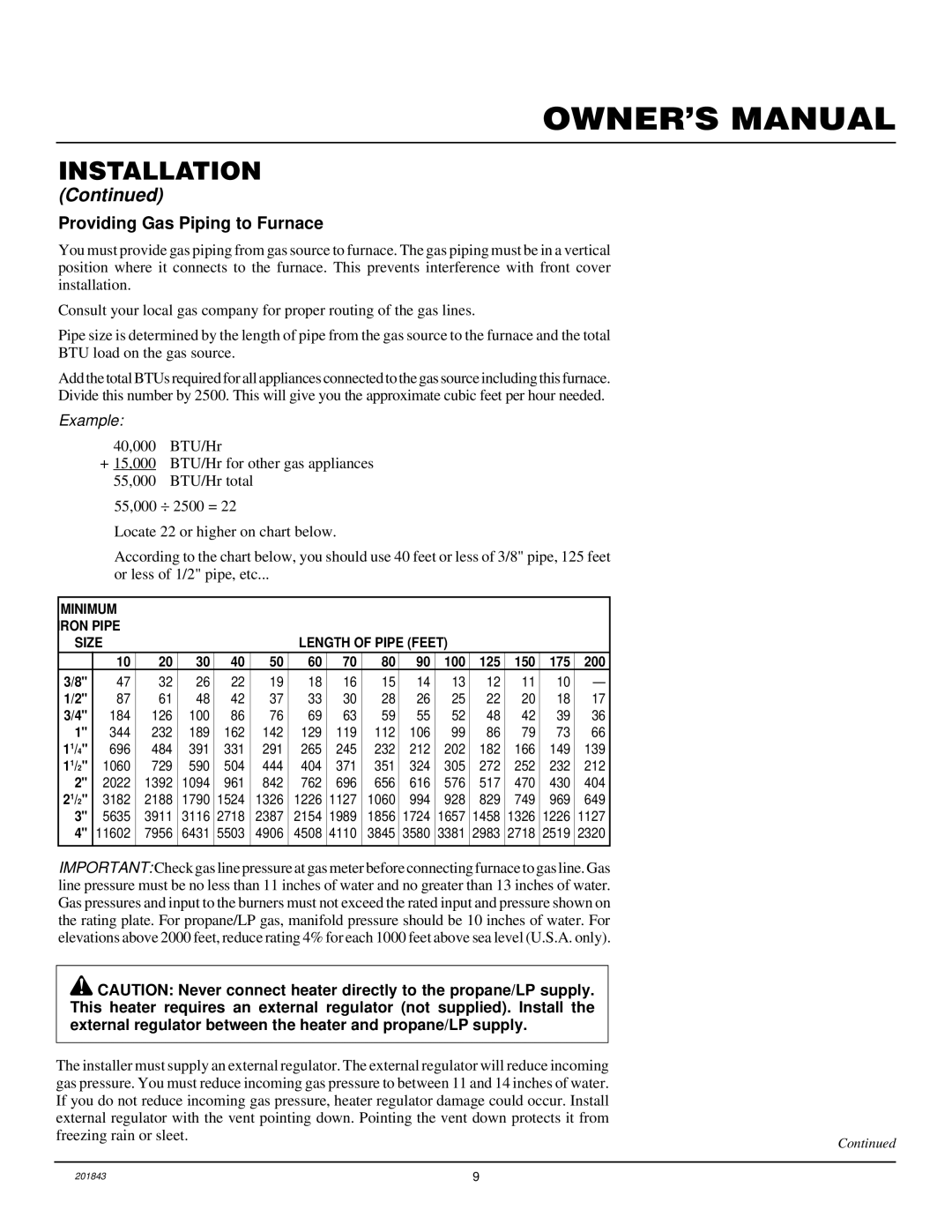
Locate 22 or higher on chart below.

According to the chart below, you should use 40 feet or less of 3/8" pipe, 125 feet or less of 1/2" pipe, etc...

MINIMUM


IRON PIPE


SIZE


LENGTH OF PIPE (FEET)


10

20

30

40

50

60

70

80

90

100

125

150

175

200

3/8"

47

32

26

22

19

18

16

15

14

13

12

11

10

1/2"

87

61

48

42

37

33

30

28

26

25

22

20

18

17

3/4"

184

126

100

86

76

69

63

59

55

52

48

42

39

36

1"

344

232

189

162

142

129

119

112

106

99

86

79

73

66

11/4"

696

484

391

331

291

265

245

232

212

202

182

166

149

139

11/2"

1060

729

590

504

444

404

371

351

324

305

272

252

232

212

2"

2022

1392

1094

961

842

762

696

656

616

576

517

470

430

404

21/2"

3182

2188

1790

1524

1326

1226

1127

1060

994

928

829

749

969

649

3"

5635

3911

3116

2718

2387

2154

1989

1856

1724

1657

1458

1326

1226

1127

4"

11602

7956

6431

5503

4906

4508

4110

3845

3580

3381

2983

2718

2519

2320


IMPORTANT: Check gas line pressure at gas meter before connecting furnace to gas line. Gas line pressure must be no less than 11 inches of water and no greater than 13 inches of water. Gas pressures and input to the burners must not exceed the rated input and pressure shown on the rating plate. For propane/LP gas, manifold pressure should be 10 inches of water. For elevations above 2000 feet, reduce rating 4% for each 1000 feet above sea level (U.S.A. only).

CAUTION: Never connect heater directly to the propane/LP supply. This heater requires an external regulator (not supplied). Install the external regulator between the heater and propane/LP supply.

The installer must supply an external regulator. The external regulator will reduce incoming gas pressure. You must reduce incoming gas pressure to between 11 and 14 inches of water. If you do not reduce incoming gas pressure, heater regulator damage could occur. Install external regulator with the vent pointing down. Pointing the vent down protects it from freezing rain or sleet.

Continued

201843

9

Page 9
Image 9
Williams 4003531, 2503531 installation manual Providing Gas Piping to Furnace, Example

2503531, 4003531 specifications

Williams 2503531,4003531 is a noteworthy product in the realm of advanced engineering and technology, often recognized for its cutting-edge features and innovative design. This product is designed to meet the demands of modern applications, bringing powerful performance and remarkable efficiency to a variety of fields.

One of the main features of the Williams 2503531,4003531 is its robust construction. Built using high-quality materials, this product is engineered to withstand rigorous conditions, ensuring longevity and reliability even in challenging environments. The incorporation of advanced manufacturing techniques contributes to its resilience, making it suitable for industrial applications where durability is crucial.

Technologically, the Williams 2503531,4003531 stands out due to its integration of smart technology. It often includes embedded sensors that allow for real-time monitoring and data analysis. This feature enhances operational efficiency by enabling proactive maintenance and reducing downtime. Users can confidently rely on up-to-date information regarding the system's performance, allowing for informed decision-making and optimizing productivity.

Another characteristic that sets the Williams 2503531,4003531 apart is its user-friendly interface. The intuitive design ensures that operators can easily navigate through various functions, minimizing the learning curve and maximizing productivity. The product is often equipped with customizable settings, allowing users to tailor its functionality according to specific operational needs.

In terms of energy efficiency, the Williams 2503531,4003531 employs advanced technologies that minimize power consumption while maintaining high performance levels. This aligns with the growing emphasis on sustainability and environmental responsibility in modern engineering solutions. By reducing energy costs, users can achieve significant savings while contributing to a greener future.

Moreover, safety features are paramount in the design of the Williams 2503531,4003531. It typically includes multiple safety mechanisms that protect both the operators and the equipment. These safety measures are in compliance with industry standards, ensuring that users can operate the machinery with confidence.

In summary, the Williams 2503531,4003531 combines durability, advanced technology, user-friendliness, energy efficiency, and robust safety features. It caters to a diverse range of applications, making it an invaluable asset in various sectors. As industries continue to evolve, products like the Williams 2503531,4003531 will play a pivotal role in shaping the future of engineering and technological solutions.