WIR TX75
Installation Procedures
Determine Coverage Area
When using the WIR TX75 transmitter in
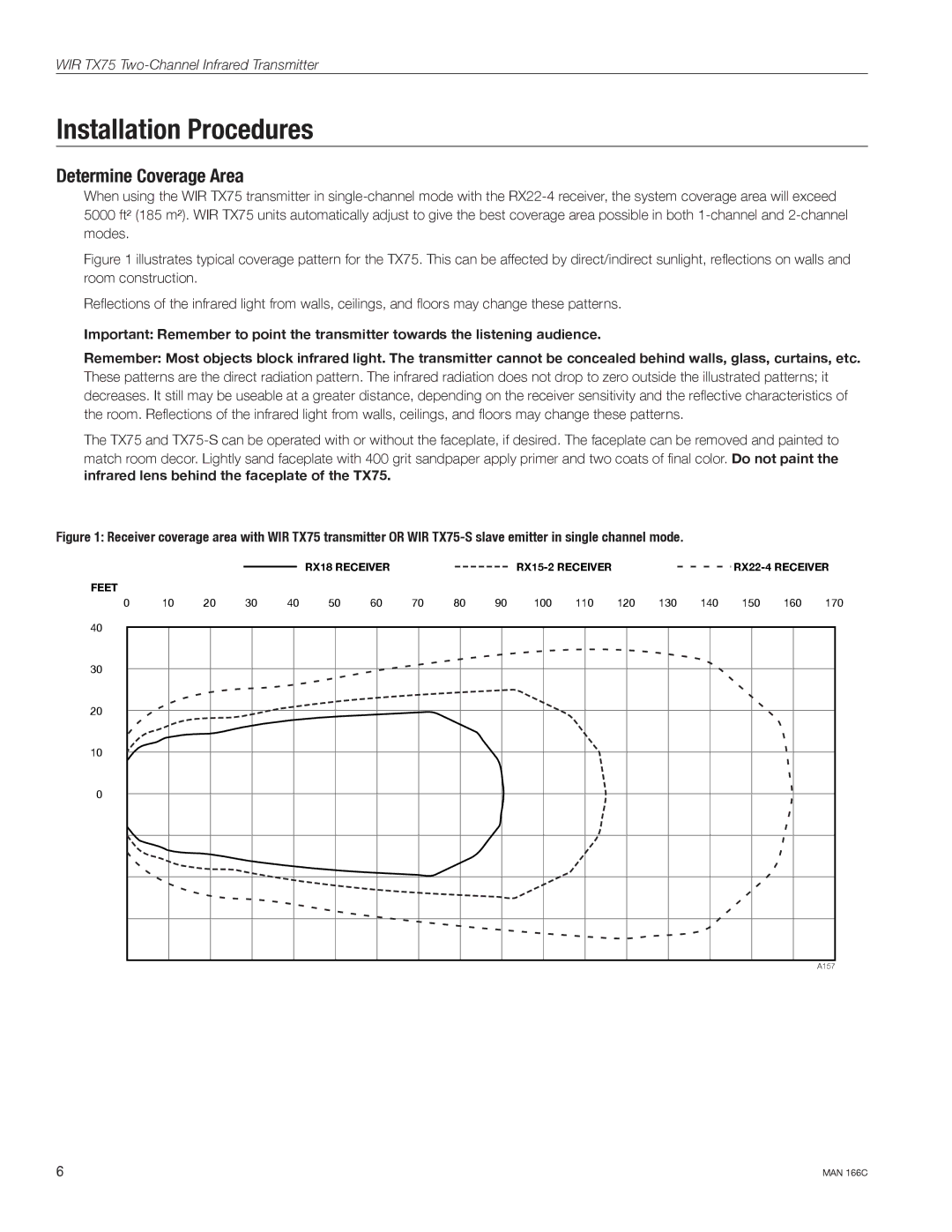
Figure 1 illustrates typical coverage pattern for the TX75. This can be affected by direct/indirect sunlight, reflections on walls and room construction.
Reflections of the infrared light from walls, ceilings, and floors may change these patterns.
Important: Remember to point the transmitter towards the listening audience.
Remember: Most objects block infrared light. The transmitter cannot be concealed behind walls, glass, curtains, etc. These patterns are the direct radiation pattern. The infrared radiation does not drop to zero outside the illustrated patterns; it decreases. It still may be useable at a greater distance, depending on the receiver sensitivity and the reflective characteristics of the room. Reflections of the infrared light from walls, ceilings, and floors may change these patterns.
The TX75 and
match room decor. Lightly sand faceplate with 400 grit sandpaper apply primer and two coats of final color. Do not paint the infrared lens behind the faceplate of the TX75.
Figure 1: Receiver coverage area with WIR TX75 transmitter OR WIR TX75-S slave emitter in single channel mode.
FEET |
|
|
|
|
| RX18 RECEIVER |
|
|
|
|
|
|
|
| ||||||
|
|
|
|
|
|
|
|
|
|
| ||||||||||
|
|
|
|
|
|
|
|
|
|
|
|
|
|
|
|
|
|
| ||
0 | 10 | 20 | 30 | 40 | 50 | 60 | 70 | 80 | 90 | 100 | 110 | 120 | 130 | 140 | 150 | 160 | 170 | |||
40 |
|
|
|
|
|
|
|
|
|
|
|
|
|
|
|
|
|
|
|
|
|
|
|
|
|
|
|
|
|
|
|
|
|
|
|
|
|
|
|
| |
30
20
10
0
A157
6 | MAN 166C |