WIR TX75
Infrared Emitter Specifications
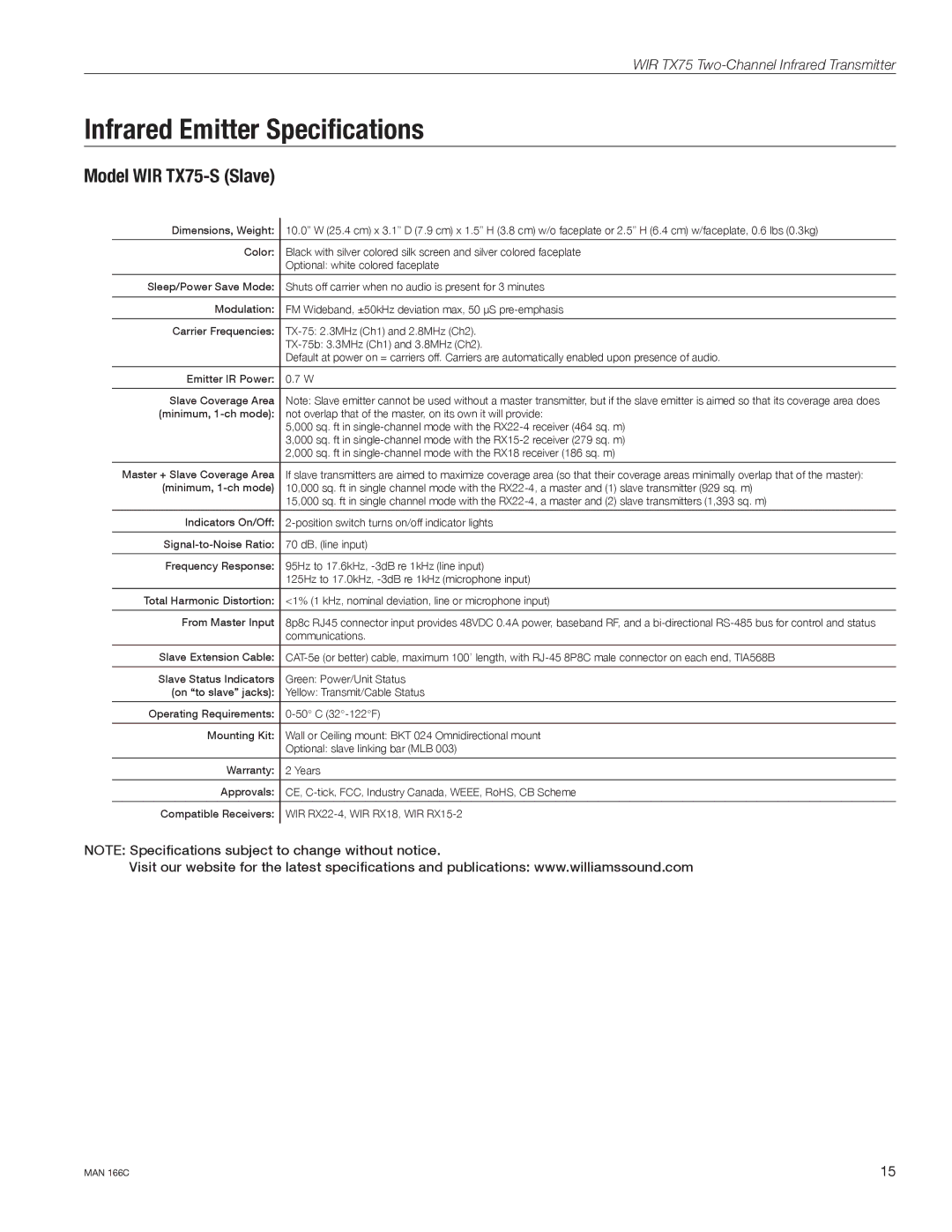
Model WIR TX75-S (Slave)
Dimensions, Weight: | 10.0” W (25.4 cm) x 3.1” D (7.9 cm) x 1.5” H (3.8 cm) w/o faceplate or 2.5” H (6.4 cm) w/faceplate, 0.6 lbs (0.3kg) |
|
|
Color: | Black with silver colored silk screen and silver colored faceplate |
| Optional: white colored faceplate |
|
|
Sleep/Power Save Mode: | Shuts off carrier when no audio is present for 3 minutes |
|
|
Modulation: | FM Wideband, ±50kHz deviation max, 50 μS |
|
|
Carrier Frequencies: | |
| |
| Default at power on = carriers off. Carriers are automatically enabled upon presence of audio. |
|
|
Emitter IR Power: | 0.7 W |
|
|
Slave Coverage Area | Note: Slave emitter cannot be used without a master transmitter, but if the slave emitter is aimed so that its coverage area does |
(minimum, | not overlap that of the master, on its own it will provide: |
| 5,000 sq. ft in |
| 3,000 sq. ft in |
| 2,000 sq. ft in |
|
|
Master + Slave Coverage Area | If slave transmitters are aimed to maximize coverage area (so that their coverage areas minimally overlap that of the master): |
(minimum, | 10,000 sq. ft in single channel mode with the |
| 15,000 sq. ft in single channel mode with the |
|
|
Indicators On/Off: | |
|
|
70 dB, (line input) | |
|
|
Frequency Response: | 95Hz to 17.6kHz, |
| 125Hz to 17.0kHz, |
|
|
Total Harmonic Distortion: | <1% (1 kHz, nominal deviation, line or microphone input) |
|
|
From Master Input | 8p8c RJ45 connector input provides 48VDC 0.4A power, baseband RF, and a |
| communications. |
|
|
Slave Extension Cable: | |
|
|
Slave Status Indicators | Green: Power/Unit Status |
(on “to slave” jacks): | Yellow: Transmit/Cable Status |
|
|
Operating Requirements: | |
|
|
Mounting Kit: | Wall or Ceiling mount: BKT 024 Omnidirectional mount |
| Optional: slave linking bar (MLB 003) |
|
|
Warranty: | 2 Years |
|
|
Approvals: | CE, |
|
|
Compatible Receivers: | WIR |
|
|
NOTE: Specifications subject to change without notice.
Visit our website for the latest specifications and publications: www.williamssound.com
MAN 166C | 15 |