NOTE:

To prevent damage in shipping, the second set of elements from the rear of the boom are folded to the opposite side.

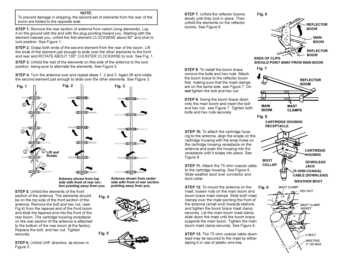
STEP 1. Remove the rear section of antenna from carton (long elements). Lay it on the ground with the end with the plug pointing toward you. Starting with the element nearest you, unfold the first element CLOCKWISE about 80° and click to lock position. See Figure 1.

STEP 7. Unfold the reflector booms slowly until they lock in place. Then unfold the elements on the reflector booms. See Figure 6.

Fig. 6


REFLECTOR


BOOM


MAIN


BOOM

STEP 2. Grasp both ends of the second element from the rear of the boom. Lift the ends of the element just enough to slide over the other elements to the front and rear and ROTATE ABOUT 100° COUNTER CLOCKWISE to lock. See Fig. 1.

ENDS OF CLIPS

REFLECTOR BOOM

STEP 3. Unfold the rest of the elements on this side of the antenna to the lock position, being sure to alternate the elements. See Figure 2.

STEP 4. Turn the antenna over and repeat steps 1, 2 and 3. Again lift and rotate the second element just enough to slide over the other elements. See Figure 3.

STEP 8. To install the boom brace remove the bolts and hex nuts. Attach the boom brace to the reflector boom first, making sure that the mast clamps

SHOULD POINT AWAY FROM MAIN BOOM

Fig. 7

Fig. 1Fig. 2

 


Fig. 3

are on the same side, see Figure 7. Do not tighten the bolt and hex nut.

STEP 9. Swing the boom brace down onto the main boom and insert the bolt and hex nut, see Figure 7. Tighten both bolts and hex nuts securely.

Fig. 8

CARTRIDGE HOUSING

RECEPTACLE


Lift and


Rotate


Antenna shown from top side with front of rear sec-


Antenna shown from under- side with front of rear section

STEP 10. To attach the cartridge hous- ing to the antenna, align the snaps on the cartridge housing with the snap holes on the cartridge housing receptacle on the antenna and push the housing into the receptacle until it snaps into place. See Figure 8.

STEP 11. Attach the 75 ohm coaxial cable to the cartridge housing. See Figure 8. Slide weather boot over connector and boot collar.

CARTRIDGE

HOUSING

BOOT DOWNLEAD

COLLARJACK

75 OHM COAXIAL CABLE (DOWNLEAD)

WEATHER BOOT

tion pointing away from you.

STEP 5. Unfold the elements of the front


section of the antenna. The elements should

Fig. 4

be on the top side of the front section of the


antenna. Remove the bolt and hex nut, (see


Fig 4) from the tapered end of the front boom


and slide the tapered end into the front of the


rear boom. The cartridge housing receptacle


on the rear section of the antenna is attached


to the bottom of the rear boom at the factory.


Replace the bolt, and hex nut. Tighten

Fig. 5

securely.

STEP 6. Unfold UHF directors, as shown in


Figure 5.


pointing away from you.

STEP 12. To mount the antenna on the Fig. 9 mast, loosen nuts on the main boom and boom brace mast clamps. Slide both mast clamps over the mast pointing the front of

the antenna (small end) towards stations and tighten the boom brace mast clamp securely. Let the main boom mast clamp slide down the mast until the boom brace supports the main boom. Tighten the main boom mast clamp securely. See Figure 9.

STEP 13. The 75 ohm coaxial cable down- lead may be secured to the mast by either taping it or use of plastic wire ties.

MAST CLAMP

HEX NUT

MAST CLAMP

INSERT

U-BOLT

MASTING 2" OD MAX.

Page 2
Image 2
Winegard HD7697P, HD7084P warranty  

HD7084P, HD7697P specifications

The Winegard HD7697P and HD7084P are two highly regarded outdoor HD antennas designed for digital television reception. These antennas are popular among cord-cutters looking to access free over-the-air (OTA) broadcast signals. Both models offer unique features, technologies, and characteristics that cater to different reception needs.

The Winegard HD7697P is an advanced outdoor antenna that amplifies signal capture and offers a range of up to 70 miles. It is engineered with a robust design that can withstand harsh weather conditions, making it suitable for various regional climates. One significant feature of the HD7697P is its patented OneLink technology, which allows for a seamless connection with multiple televisions without the need for an additional splitter. This antenna also includes a heavy-duty mounting bracket, ensuring stability and reliability when installed on rooftops or poles.

Equipped with a multi-directional reception pattern, the HD7697P can easily pick up signals from multiple broadcast towers without necessitating a complex installation process. The antenna’s sleek, low-profile design not only enhances aesthetics but also helps reduce wind resistance, further improving its durability. The embedded 4G LTE filter minimizes interference from mobile signals, ensuring a clearer reception with fewer interruptions.

On the other hand, the Winegard HD7084P is tailored for urban and suburban settings where signals are generally stronger. This antenna boasts a range of up to 50 miles and shares many technological features with the HD7697P. It adopts a compact design that provides easier installation while still delivering exceptional performance. The HD7084P is built with a lightweight structure without compromising on signal reception quality.

Like the HD7697P, the HD7084P is equipped with multi-directional capabilities, allowing users to receive signals from various directions. Its robust construction makes it resistant to weather-related damage, making it a practical choice for outdoor use. The antenna also includes a 4G LTE filter to enhance picture quality by reducing interference.

In summary, both the Winegard HD7697P and HD7084P offer excellent options for consumers seeking reliable HD antenna solutions. With modern technologies such as multi-directional reception and advanced filtering, these antennas are designed to ensure optimal performance, providing users with access to local channels and high-definition programming without the costs associated with cable services.