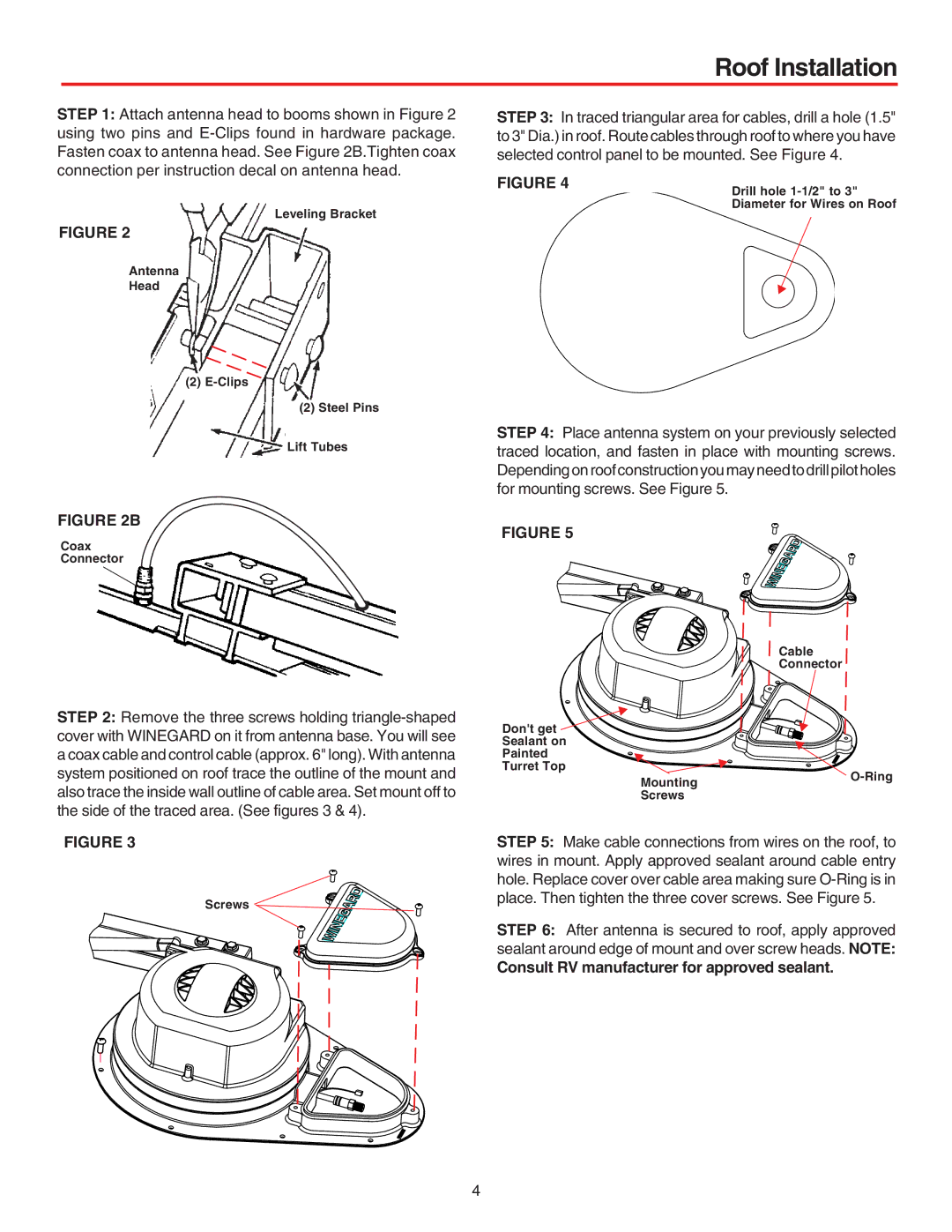
STEP 1: Attach antenna head to booms shown in Figure 2 using two pins and
Leveling Bracket
FIGURE 2
Antenna
Head
(2)
(2) Steel Pins
Lift Tubes
FIGURE 2B
Coax
Connector
Roof Installation
STEP 3: In traced triangular area for cables, drill a hole (1.5" to 3" Dia.) in roof. Route cables through roof to where you have selected control panel to be mounted. See Figure 4.
FIGURE 4
Drill hole
Diameter for Wires on Roof
c
STEP 4: Place antenna system on your previously selected traced location, and fasten in place with mounting screws. Dependingonroofconstructionyoumayneedtodrillpilotholes for mounting screws. See Figure 5.
FIGURE 5
STEP 2: Remove the three screws holding
Don't get Sealant on Painted Turret Top
c |
|
c | c |
Mounting |
|
Screws |
|
Cable
Connector
![]()
![]()
![]()
![]()
![]()
![]()
![]()
![]() c
c![]()
![]()
![]()
![]()
![]()
![]()
![]()
![]()
![]() c
c![]()
![]()
![]()
![]()
FIGURE 3
Screws ![]()
![]()
![]()
![]()
![]()
![]()
![]()
![]()
STEP 5: Make cable connections from wires on the roof, to wires in mount. Apply approved sealant around cable entry hole. Replace cover over cable area making sure
STEP 6: After antenna is secured to roof, apply approved sealant around edge of mount and over screw heads. NOTE:
Consult RV manufacturer for approved sealant.
4
