GRIDDLES MOUNTED ON STANDS WITH CASTERS |
|
Griddles mounted on stands with casters must use a |
|
flexible connector (not supplied) that complies with the |
|
Standard for Connectors for Movable Gas Appliances |
|
ANSI Z21.69•CSA6.16, and a |
|
that complies with Gas Fuel, ANSI Z21.3•CSA6.9. In |
|
addition, adequate means must be provided to limit |
|
movement of the appliance without depending on the |
|
connector and the |
|
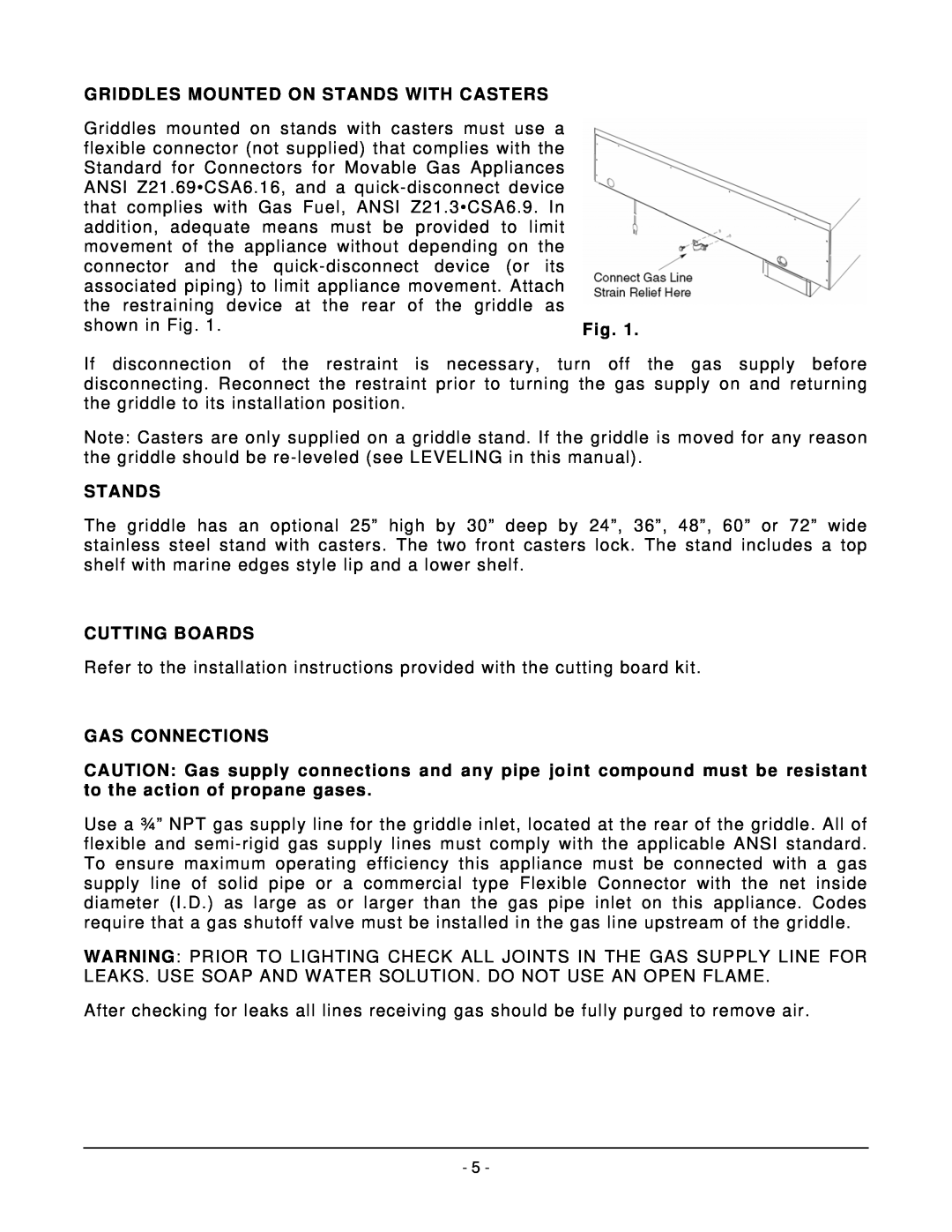
associated piping) to limit appliance movement. Attach |
|
the restraining device at the rear of the griddle as |
|
shown in Fig. 1. | Fig. 1. |
If disconnection of the restraint is necessary, turn off the gas supply before disconnecting. Reconnect the restraint prior to turning the gas supply on and returning the griddle to its installation position.
Note: Casters are only supplied on a griddle stand. If the griddle is moved for any reason the griddle should be
STANDS
The griddle has an optional 25” high by 30” deep by 24”, 36”, 48”, 60” or 72” wide stainless steel stand with casters. The two front casters lock. The stand includes a top shelf with marine edges style lip and a lower shelf.
CUTTING BOARDS
Refer to the installation instructions provided with the cutting board kit.
GAS CONNECTIONS
CAUTION: Gas supply connections and any pipe joint compound must be resistant to the action of propane gases.
Use a ¾” NPT gas supply line for the griddle inlet, located at the rear of the griddle. All of flexible and
WARNING: PRIOR TO LIGHTING CHECK ALL JOINTS IN THE GAS SUPPLY LINE FOR LEAKS. USE SOAP AND WATER SOLUTION. DO NOT USE AN OPEN FLAME.
After checking for leaks all lines receiving gas should be fully purged to remove air.
- 5 -
