RD60, RD72, RDC54 specifications
Woods Equipment is renowned for its innovative and efficient landscaping solutions, and the RD series of rotary cutters exemplifies this reputation. The RD60, RDC54, and RD72 models are designed to cater to varying needs in land management, providing robust performance and ease of use.The RD60 model stands out for its impressive cutting width of 60 inches, making it an ideal choice for commercial and residential applications. Its heavy-duty construction ensures longevity, with a rugged deck design that can withstand challenging terrains. The RD60 features a slip clutch protection system that prevents damage to the cutter during operation by absorbing shock loads. Additionally, its adjustable skids allow for varied cutting heights, making it versatile for different types of vegetation.
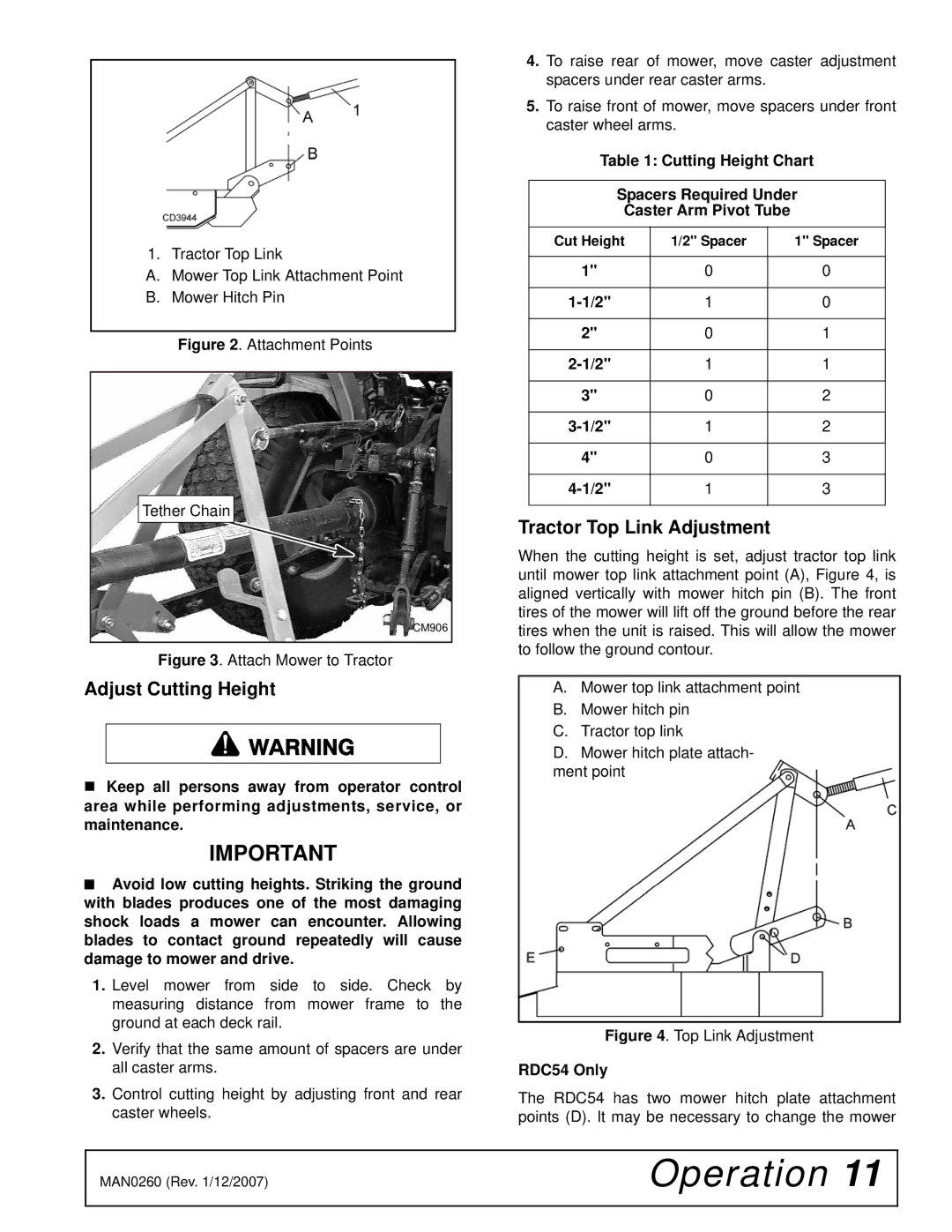
RDC54, while slightly smaller with a cutting width of 54 inches, is designed with a focus on efficiency and maneuverability. Its compact build makes it perfect for smaller properties or tight spaces. The RDC54 boasts a quick-attach mounting system, enabling users to easily connect and disconnect the cutter from their tractor. Users can also appreciate the innovative dual-blade design that enhances cutting performance, resulting in a finer mulch for improved decomposition when tackling thicker grass and brush.
On the other hand, the RD72 takes productivity to the next level with its 72-inch cutting width. This model is particularly favored by professionals looking to cover large areas quickly. Equipped with an advanced drive system, the RD72 delivers consistent power to its blades, ensuring clean cuts even in tough conditions. The model features a robust frame and reinforced side panels, making it suitable for heavy-duty applications. Furthermore, its quick-adjustment feature allows operators to change the cutting height smoothly and efficiently, maximizing versatility.
All models in the RD series incorporate cutting-edge technology, such as optimized blade design and improved airflow, which contributes to a cleaner and more efficient cut. Durability is a common theme across the series, with high-quality materials used throughout the construction ensuring these rotary cutters can handle the rigors of daily use.
In conclusion, Woods Equipment's RD60, RDC54, and RD72 rotary cutters offer a blend of durability, efficiency, and advanced features, catering to the diverse needs of landscape professionals and property owners alike. Whether the job requires finesse or brute force, there's an RD model built to deliver results.