TC68, TC60, TC74, TCR74, TCR68 specifications
Woods Equipment has established a reputation for producing high-quality agricultural and landscaping equipment, and their line of TCR and TC series implements exemplifies this commitment to quality and performance. The TCR68, TCR74, TCR60, TC60, and TC68 models are notable products within this range, tailored to meet the diverse needs of operators in various situations.The TCR series, including the TCR68 and TCR74, is designed as a compact rotary cutter that efficiently handles heavy grass and brush. One of the standout features of the TCR series is its robust construction, incorporating a durable steel frame and high-performance blades that make it highly effective in dense growth areas. The TCR models are equipped with a flexible hitch system, allowing for easy attachment to a range of tractors, delivering exceptional maneuverability while enhancing productivity on any job site.
The TCR68, known for its 68-inch cutting width, is perfect for medium-sized properties, providing an excellent balance between size and power. Conversely, the TCR74 with a 74-inch width caters to larger open areas, ensuring fewer passes are needed for efficiency. Both models feature a maximum cutting height adjustment, catering to the specific needs of users for different types of landscaping jobs.
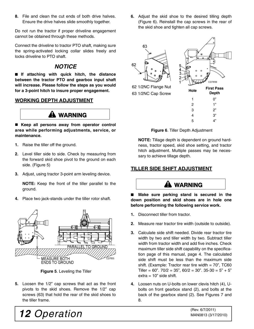
The TC series, which includes the TC60 and TC68, takes versatility to the next level. These models serve as versatile tillage tools. The TC60 features a 60-inch working width, making it ideal for smaller gardens and farms. Built with a robust frame and quality components, it ensures long-lasting performance. The TC68 model offers an increased working width of 68 inches, appealing to larger landowners who require fast and efficient soil preparation.
Both TC models emphasize ease of use, with user-friendly adjustments for depth and tilling intensity. They feature advanced technologies such as automatic depth control, ensuring consistent tillage results across varying soil conditions.
In conclusion, whether choosing the TCR series for cutting or the TC series for tilling, Woods Equipment provides reliable and effective solutions. These models combine advanced engineering, durable materials, and innovative features, positioning them as go-to implements for agricultural and landscaping professionals alike. Their commitment to performance and reliability continues to make Woods Equipment a trusted name in the industry.

