ADJUSTMENTS
Table Adjustments
The table can be adjusted for height, rotation and angle. Follow these instructions to adjust height:
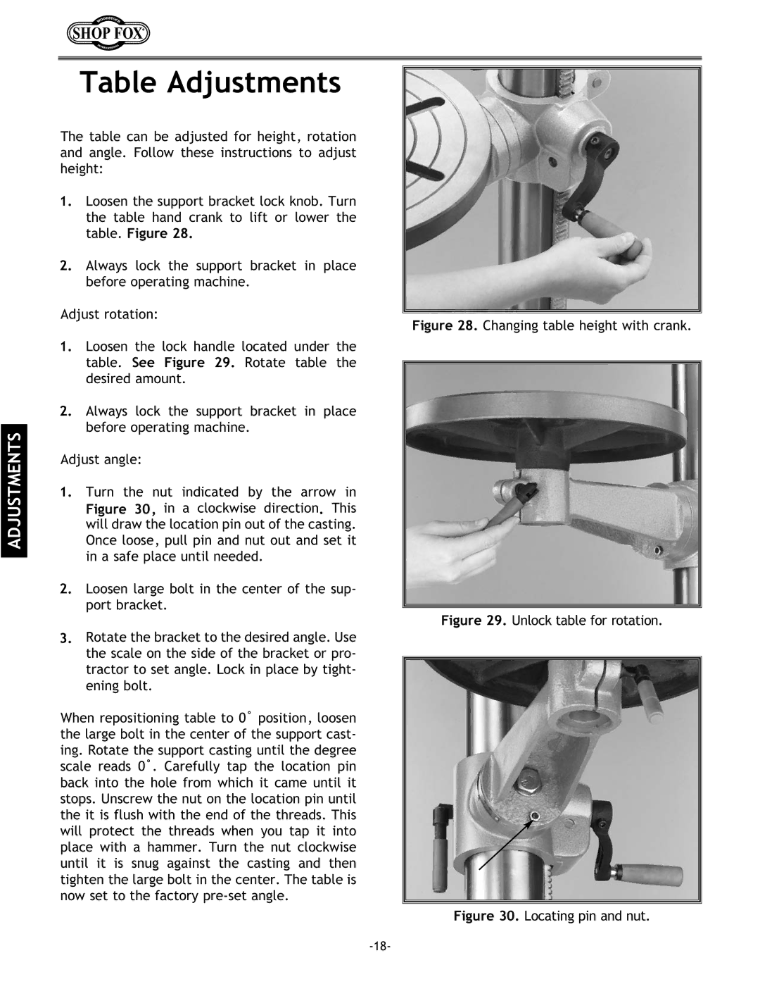
1.Loosen the support bracket lock knob. Turn the table hand crank to lift or lower the table. Figure 28.
2.Always lock the support bracket in place before operating machine.
Adjust rotation:
1.Loosen the lock handle located under the table. See Figure 29. Rotate table the desired amount.
2.Always lock the support bracket in place before operating machine.
Adjust angle:
1.Turn the nut indicated by the arrow in Figure 30, in a clockwise direction. This will draw the location pin out of the casting. Once loose, pull pin and nut out and set it in a safe place until needed.
2.Loosen large bolt in the center of the sup- port bracket.
3.Rotate the bracket to the desired angle. Use the scale on the side of the bracket or pro- tractor to set angle. Lock in place by tight- ening bolt.
When repositioning table to 0˚ position, loosen the large bolt in the center of the support cast- ing. Rotate the support casting until the degree scale reads 0˚. Carefully tap the location pin back into the hole from which it came until it stops. Unscrew the nut on the location pin until the it is flush with the end of the threads. This will protect the threads when you tap it into place with a hammer. Turn the nut clockwise until it is snug against the casting and then tighten the large bolt in the center. The table is now set to the factory
