ASSEMBLY INSTRUCTIONS
ASSEMBLY
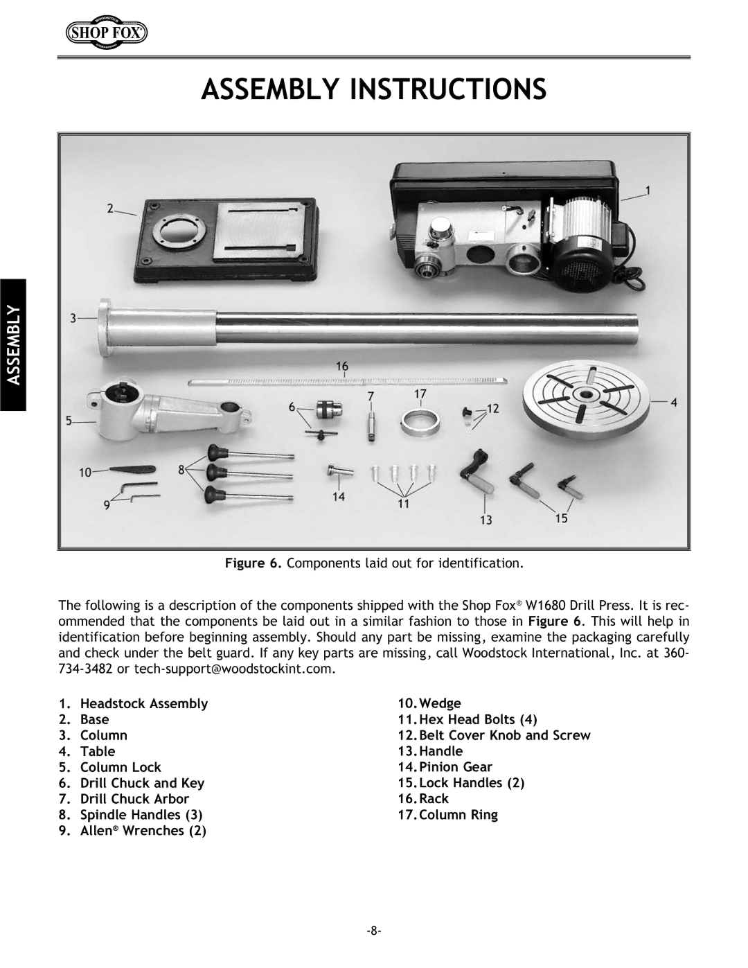
Figure 6. Components laid out for identification.
The following is a description of the components shipped with the Shop Fox® W1680 Drill Press. It is rec- ommended that the components be laid out in a similar fashion to those in Figure 6. This will help in identification before beginning assembly. Should any part be missing, examine the packaging carefully and check under the belt guard. If any key parts are missing, call Woodstock International, Inc. at 360- 734-3482 or tech-support@woodstockint.com.
1. | Headstock Assembly | 10.Wedge |
2. | Base | 11.Hex Head Bolts (4) |
3. | Column | 12.Belt Cover Knob and Screw |
4. | Table | 13.Handle |
5. | Column Lock | 14.Pinion Gear |
6. | Drill Chuck and Key | 15.Lock Handles (2) |
7. | Drill Chuck Arbor | 16.Rack |
8. | Spindle Handles (3) | 17.Column Ring |
9. | Allen® Wrenches (2) |
|
