W1764 Power Feeder
SETUP
SETUP
Unpacking
This machine has been carefully packaged for safe trans- portation. If you notice the machine has been damaged during shipping, please contact your authorized Shop Fox dealer immediately.
Inventory
The following is a description of the main components shipped with the Model W1764. Lay the components out to inventory them.
Note: If you can't find an item on this list, check the mounting location on the machine or examine the pack- aging materials carefully. Occasionally we
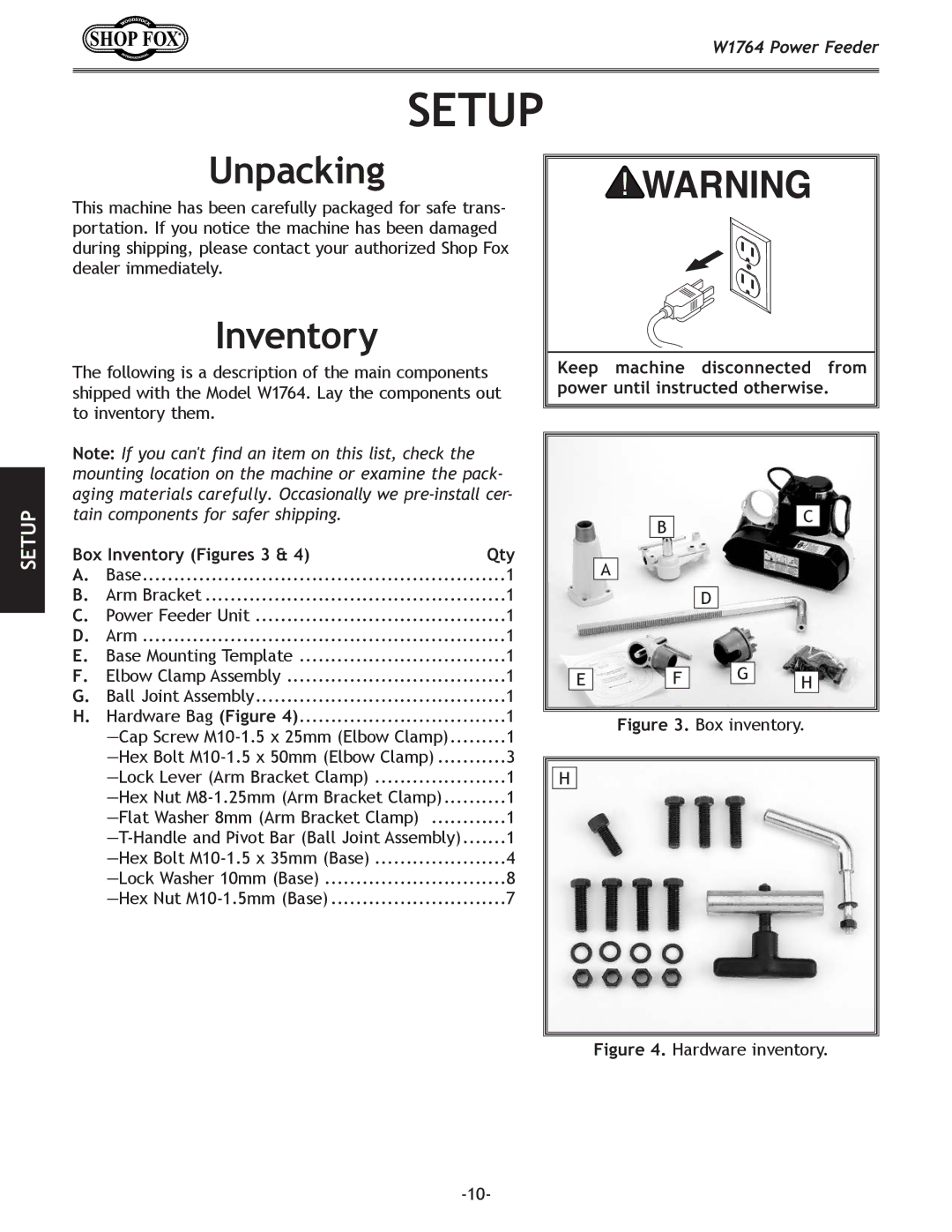
Box Inventory (Figures 3 & 4) | Qty | |
A. | Base | 1 |
B. | Arm Bracket | 1 |
C. | Power Feeder Unit | 1 |
D. | Arm | 1 |
E. | Base Mounting Template | 1 |
F. | Elbow Clamp Assembly | 1 |
G. | Ball Joint Assembly | 1 |
H. | Hardware Bag (Figure 4) | 1 |
| 1 | |
| 3 | |
| 1 | |
| 1 | |
| 1 | |
| 1 | |
| 4 | |
| 8 | |
| 7 | |
Keep machine disconnected from power until instructed otherwise.
|
| C |
B |
| |
|
|
A
D
|
|
|
| G |
|
|
E |
| F |
|
| ||
|
|
| H | |||
|
|
| ||||
|
|
|
|
|
|
|
Figure 3. Box inventory.
H