INSTALLATION INSTRUCTIONS
172-77
XTRA LINK® 2
REMOTE CONTROL EXTENSION SYSTEM
The Xtra Link 2 system provides full remote control operation of a satellite receiver, cable box or VCR from a second room by sharing the coaxial cable connecting your video equipment to this second room’s TV.
The
IR Receivers
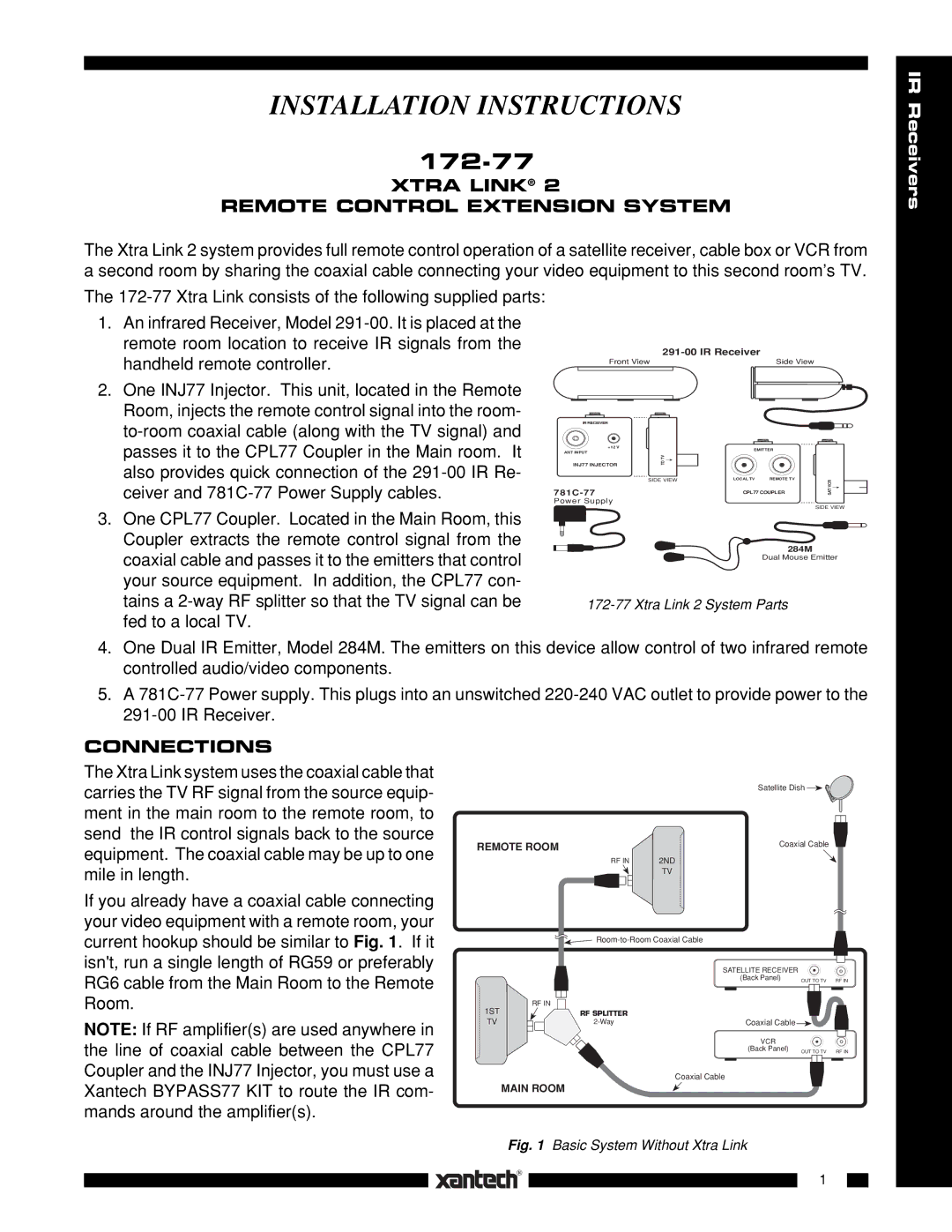
1.An infrared Receiver, Model
2.One INJ77 Injector. This unit, located in the Remote Room, injects the remote control signal into the room-
3.One CPL77 Coupler. Located in the Main Room, this Coupler extracts the remote control signal from the coaxial cable and passes it to the emitters that control your source equipment. In addition, the CPL77 con- tains a
|
|
| |
Front View | Side View |
| |
IR RECEIVER |
|
|
|
+12 V |
| EMITTER |
|
ANT INPUT |
|
| |
TO TV |
|
| |
INJ77 INJECTOR |
|
| |
|
|
| |
| SIDE VIEW | LOCAL TV REMOTE TV | SAT/VCR |
| CPL77 COUPLER | ||
Power Supply
SIDE VIEW
284M
Dual Mouse Emitter
4.One Dual IR Emitter, Model 284M. The emitters on this device allow control of two infrared remote controlled audio/video components.
5.A
CONNECTIONS
The Xtra Link system uses the coaxial cable that carries the TV RF signal from the source equip- ment in the main room to the remote room, to send the IR control signals back to the source equipment. The coaxial cable may be up to one mile in length.
If you already have a coaxial cable connecting your video equipment with a remote room, your current hookup should be similar to Fig. 1. If it isn't, run a single length of RG59 or preferably RG6 cable from the Main Room to the Remote Room.
NOTE: If RF amplifier(s) are used anywhere in the line of coaxial cable between the CPL77 Coupler and the INJ77 Injector, you must use a Xantech BYPASS77 KIT to route the IR com- mands around the amplifier(s).
|
| Satellite Dish |
| |
REMOTE ROOM |
| Coaxial Cable |
| |
| RF IN | 2ND |
|
|
|
| TV |
|
|
|
|
| ||
|
| SATELLITE RECEIVER |
|
|
|
| (Back Panel) | OUT TO TV | RF IN |
RF IN |
|
|
|
|
1ST | RF SPLITTER |
|
|
|
TV | Coaxial Cable |
|
| |
|
| VCR |
|
|
|
| (Back Panel) | OUT TO TV | RF IN |
Coaxial Cable
MAIN ROOM
Fig. 1 Basic System Without Xtra Link
1